Fuel Cell with Integrated Fluid Management

a fuel cell and fluid management technology, applied in the field of fuel cells, can solve the problems of large bulky gas management system, large bulky and a large amount of fuel cell in the stacking direction

Active Publication Date: 2010-07-15
MICHELIN & CO CIE GEN DES ESTAB MICHELIN +1
View PDF12 Cites 9 Cited by
  • Summary
  • Abstract
  • Description
  • Claims
  • Application Information

AI Technical Summary

Benefits of technology

[0011]Thanks to the invention, it is possible to integrate in said endplates, preferably in one of the two, a fluid management function by accommodating some of the elements necessary for the fluid management, preferably all the elements actively involved in the management of all the fluids. This is done by increasing the thickness of such an endplate, which can be prejudicial to the mechanical function of the endplate or plates, while enabling a simple machining of the endplate and a simple and robust assembly of various elements inside the latter.
[0012]This solution offers substantial advantages in terms of volume, weight saving, reliability and even manufacturing costs. Furthermore, it enables an interface to be created easily between the fuel cell and the vehicle in which it is installed using self-sealing couplings for the fluids, and plug-in electrical connectors. Advantageously, the electrical connectors and the couplings can be arranged so that the cell, in which the fluid management system is integrated, can easily be installed in and removed from the vehicle in order to facilitate the servicing, repair or replacement of the fuel cell.
[0014]It is especially advantageous to fit in or integrate on one of the endplates elements for recycling the gases not consumed by the cell. These are, for example, a Venturi-effect device making it possible, by means of a new gas flow, to suck up the gas leaving the cell and recirculate it in the latter. Preferably, elements for eliminating the water produced by the cell are fitted on or integrated in one of the endplates.

Problems solved by technology

This requires a fairly complex and bulky gas management system, generally as bulky as the cell itself.
However, according to the technology described, the elements for managing the fluids used by the cell are divided between a number of plates which are arranged in the direction of stacking, which leads to a substantial increase in the bulk of the cell in the stacking direction.

Method used


Image

  • Fuel Cell with Integrated Fluid Management
  • Fuel Cell with Integrated Fluid Management
  • Fuel Cell with Integrated Fluid Management

Examples


Embodiment Construction

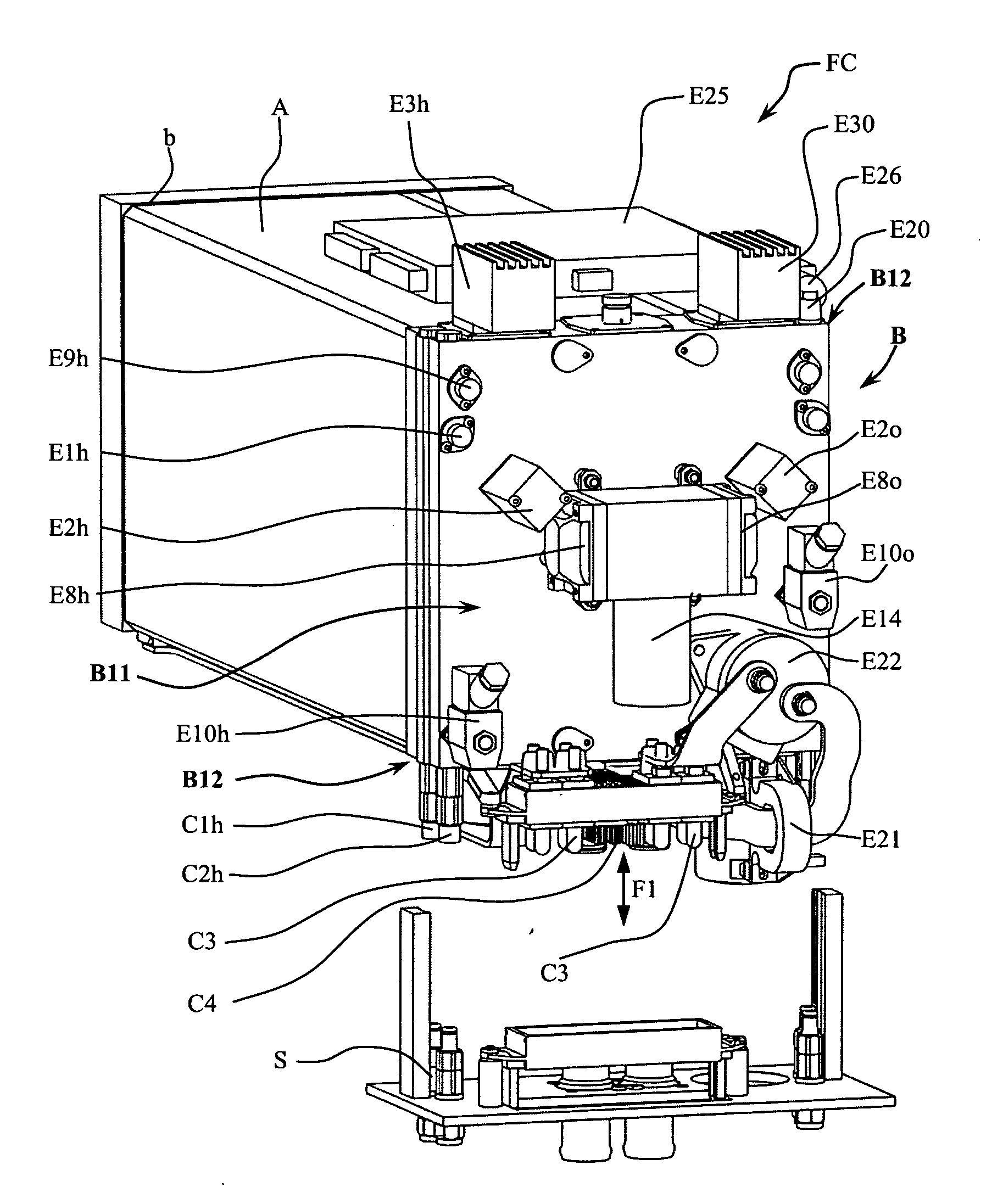
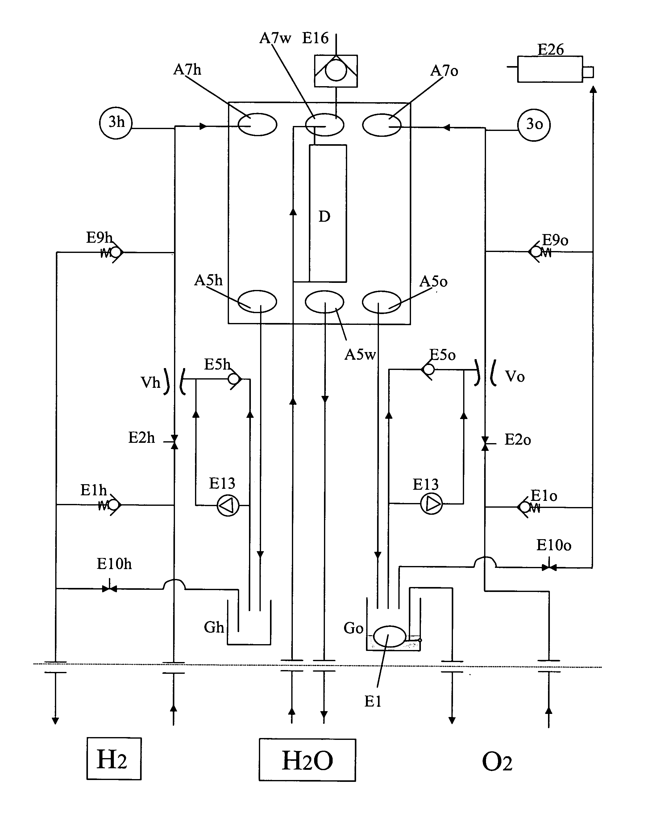
[0038]Before beginning the detailed description, the reader's attention is drawn to a notation convention for the figure indexes. Indexes beginning with the letter “P” denote a perforation, a duct, a cylindrical bore, a hole or an orifice in an endplate. Consider the example of an orifice through which a fluid enters a fuel cell. This is denoted “P7” in a generic way, that is, regardless of the fluid concerned. The index ends with the letter “o” to indicate more specifically the gas, oxygen or air, the letter “h” to indicate more specifically hydrogen gas and the letter “w” to indicate more specifically the coolant. Indexes beginning with the letter “A” refer to the stack of individual cells forming the fuel cell (commonly referred to as “stack”). Indexes beginning with the letter “C” denote a connector, whether electrical or for gas or coolant. Indexes beginning with the letter “E” denote an element belonging to the management system for one of the fluids. If an index beginning wit...


PUM

PropertyMeasurementUnit
lengthaaaaaaaaaa
currentaaaaaaaaaa
power densitiesaaaaaaaaaa

Abstract

A fuel cell (FC) comprising a stack (A) of bipolar plates and ion exchange membranes arranged alternately, the stack (A) being clamped between two endplates (B and C), the stack (A) comprising feed and return ducts for the fluids required for the operation of the cell, said fluids comprising at least one fuel gas, the ducts communicating with a fluid management system comprising elements for controlling certain operating parameters, elements for recycling gases not consumed by the cell and elements for eliminating the water produced by the cell, said installation comprising connections for feeding gases to the cell, in which the fluid management system is at least partly integrated inside one of the endplates.

Description

FIELD OF THE INVENTION[0001]The present invention relates to fuel cells. More particularly, it relates to the gas and coolant feed circuits of a fuel cell.PRIOR ART[0002]It is known that the fuel cell has to be fed with hydrogen and air or pure oxygen. Generally, it must be cooled given the power densities sought; to this end, preferably, the cell is passed through by a coolant such as water. Furthermore, certain important gas management parameters must be controlled, such as gas pressure, gas temperature, gas humidity, gas recirculation rate. This requires a fairly complex and bulky gas management system, generally as bulky as the cell itself.[0003]A fuel cell comprises a stack of bipolar plates and ion exchange membranes arranged alternately. The stack is clamped between two endplates. The fluid feed and return ducts are generally arranged parallel to the stacking direction and terminate at the endplates or at one of them, where they join ducts connecting the stack to said gas man...

Claims


Application Information

Patent Timeline
Patent Type & Authority Applications(United States)
IPC IPC(8): H01M8/04H01M8/02
CPCH01M8/0202H01M8/04097Y02E60/50H01M8/247H01M8/04156H01M8/04H01M8/24
Inventor OLSOMMER, DAVIDLAURENT, DANIELLEROY, CEDRIC
Owner MICHELIN & CO CIE GEN DES ESTAB MICHELIN
Why Eureka
Try Eureka