Air energy reduction method and apparatus using waste heat from condensers or other low grade heat

a waste heat and air energy technology, applied in the field of air energy reduction methods and equipment using waste heat from condensers or other low grade heat, can solve the problems of requiring dedicated thermal input, accompanied by heat increase, and achieve the effect of reducing relative humidity, increasing moisture removal efficiency, and reducing heat loss

Inactive Publication Date: 2010-07-15
ALBERS WALTER F
View PDF5 Cites 10 Cited by
  • Summary
  • Abstract
  • Description
  • Claims
  • Application Information

AI Technical Summary

Benefits of technology

[0006]The present invention combines dehumidification by employing a liquid desiccant and cooling by means of heat exchange with a saturated air stream in a staged manner that allows for close temperature approaches. The invention is generally carried out through utilization of three air streams. The first ambient air flow is augmented in temperature by a low temperature waste heat source. In many cases this air exits from an air conditioner condenser if the condenser is air cooled or air in heat exchange between the liquid desiccant and the hot water source by means of liquid-to-liquid heat exchangers if the condenser is cooled with water. The amount of heat rejected to the condenser is equal to the cooling capacity of the air conditioner plus the heat generated by the inefficiency of the compressor system, an amount equal to at least 10 percent of the cooling capacity. This heated air can evaporate water from a liquid desiccant owing to its reduced relative humidity. This regeneration air stream is exhausted to the environment at the same energy content as at its entrance but with at a lower temperature and with a higher moisture level. The liquid desiccant then contacts a separate ambient air stream, known as the supply air stream, and after removing moisture from this air stream is returned for regeneration. As the desiccant removes moisture from this supply air stream the energy of this air stream remains constant with the energy removed by moisture deleted balanced by energy related to its rise in temperature. The effect of this temperature increase of this supply air is mitigated by utilization of a third air stream that is maintained in a near saturated condition, in this case substituting moisture for heat. This air stream passes counter-currently in a staged manner and the cooled water, coming into balance with the reduced temperature caused by water evaporation into the air stream, is in liquid-to-liquid heat exchange with the liquid desiccant. Heat is then exchanged between the liquid desiccant and the supply air flow owing to direct contact. Heat of dehydration of the supply air is mostly transferred to this saturated air stream and depending on its wet bulb temperature most likely will reduce temperature of the supply air to less than ambient air conditions. This temperature reduction causes the relative humidity of the air to increase thereby increasing the effectiveness of moisture removal by the liquid desiccant.
[0007]The heat and mass of each air stream should not be mixed during passage through the device of the current invention as when in heat exchange with another air stream the driving force or temperature differential between air streams would be significantly reduced. As an example, an air stream with entering temperatures of 90 degrees F. and transferring heat providing an exit air temperatures of 70 degrees F. would have an a average temperature of 80 degrees F. Were two stages employed, the average of the uppermost stage would be approximately 85 degrees F. and the lower stage 75 degrees F. thus providing both higher and lower temperature heat exchange possibilities. Without staging, the moisture content of an air stream would be blended thus averaging relative humidity of an air stream as well as its temperature. This mixing is largely prevented in the process of this invention and is provided by the development of stages, each with unique properties of heat and mass. Each stage contains a basin that is connected to a separate pump. The pumped basin liquid from a supply air stage is directed through a liquid-to-liquid heat exchanger that exchanges heat with a correspondent liquid from a saturated air stage. After passage through the liquid-to-liquid heat exchanger caused by a dedicated pump, liquids are distributed upon media such as that found in evaporative coolers or in small cooling towers where the liquids are in contact with the air flow before falling into the basin thereby providing contact between the liquid and the air stream. A small stream of desiccant is allowed to flow between stages of the supply air stream before its return to contact the regenerative air stream. This heated regenerative air stream is likewise segregated into stages in order that each stage can maintain its own temperature and relative humidity composition. In the same manner as in the supply air stream, a small flow of desiccant is allowed to course counter-currently to the air stream with the air stream being first in contact with the coolest and highest relative humidity air progressively flowing to contact the highest temperature of the air stream that has the lower relative humidity.

Problems solved by technology

Operation of these wheels is adiabatic meaning that the energy of the air remains constant thus moisture removal is accompanied by an increase in heat.
The major disadvantage of the existing technologies is that all of them require a dedicated thermal input in order to be functional.

Method used


Image

  • Air energy reduction method and apparatus using waste heat from condensers or other low grade heat
  • Air energy reduction method and apparatus using waste heat from condensers or other low grade heat

Examples


Embodiment Construction

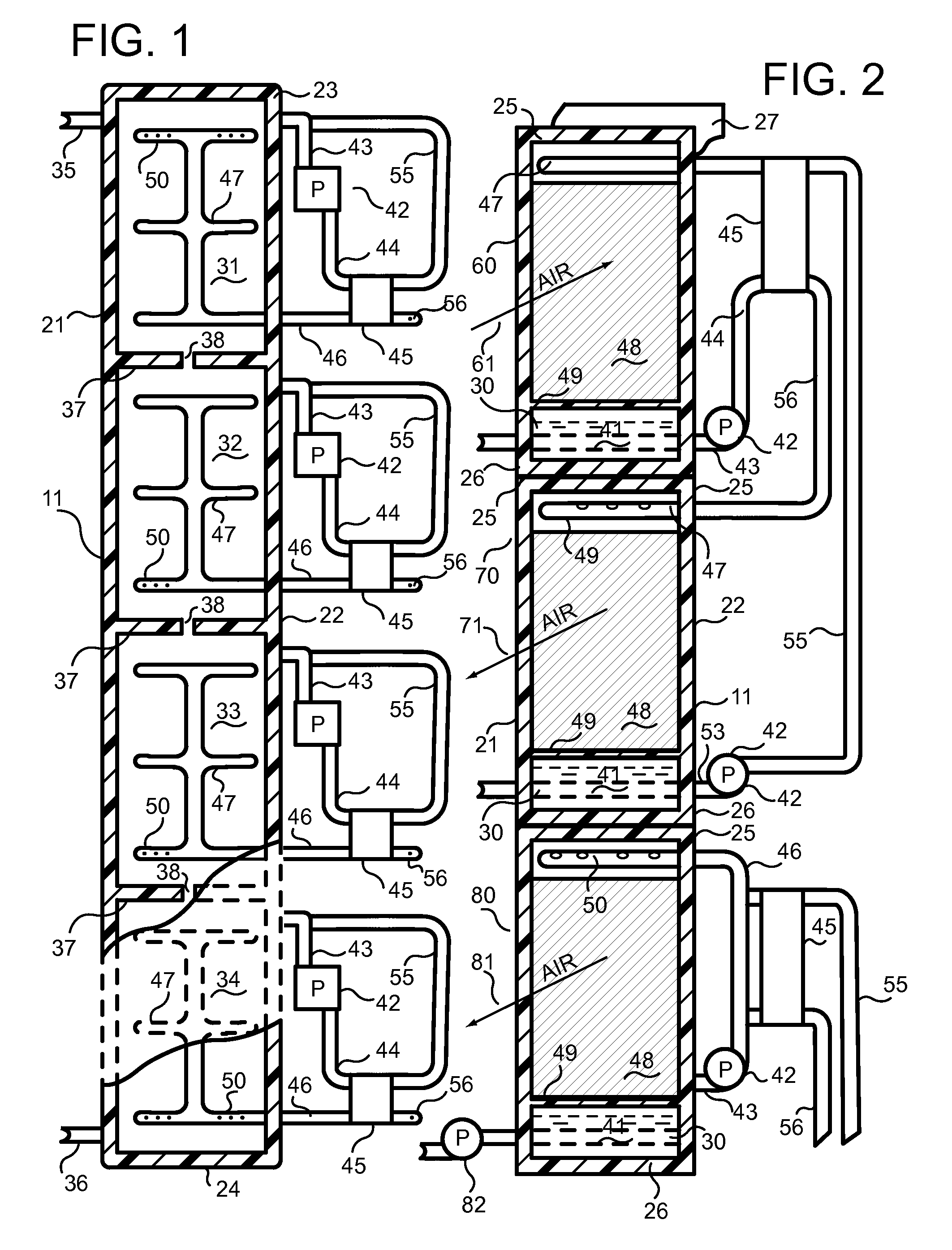
[0012]The apparatus for implementing the invention consists of a staged regenerator for removing moisture from a liquid desiccant, a staged air dehumidifier and cooler removing moisture from an air stream, and a staged saturator that maintains an air stream in a near saturated condition while exchanging heat with the dehumidifier and cooler. These three modules are generally placed in a horizontal position and they may be stacked one on the other or they may be physically separated from each other as long as they are thermally connected thermally or by means of a flow of desiccant. Each module consists of a number of stages with each stage consisting of wetting media, dedicated basin, pump and access to a liquid flow. The stages in two of the modules are thermally connected by liquid-to-liquid heat exchangers and two modules are connected by desiccant flow. Each module contains an air movement means that allows a supply of air that is separate from the other modules wherein the flow...


PUM


Abstract

The present invention provides a process for utilizing waste heat released by condensers of conventional air conditioning systems and more particularly using this low grade heat or other low grade sources that are slightly above ambient air temperatures to alter concentration of a liquid desiccant that contacts an ambient air stream thereby reducing its relative humidity while its temperature is controlled and generally reduced by heat exchange with another air stream that is saturated with water.

Description

CROSS-REFERENCE TO RELATED APPLICATION[0001]This application claims the benefit of U.S. Provisional Patent Application Ser. No. 61 / 204,705, filed Jan. 9, 2009.FIELD OF THE INVENTION[0002]The present invention relates to a process for utilizing waste heat released by condensers of conventional air conditioning systems and more particularly using this low grade heat or other low grade sources that are slightly above ambient air temperatures to alter concentration of a liquid desiccant that contacts an ambient air stream thereby reducing its relative humidity while its temperature is controlled and generally reduced by heat exchange with another air stream that is saturated with water.BACKGROUND OF THE INVENTION[0003]Concerns related to expanding utilization of electrical energy along with related cost issues have caused increased interest in energy efficiency. A related concern is limiting emissions from electrical generating plants owing to greenhouse gas issues. A further concern is...

Claims


Application Information

Patent Timeline
IPC IPC(8): F25D17/06F25D17/04F25B15/00
CPCF24F3/1417
Inventor ALBERS, WALTER F.
Owner ALBERS WALTER F
Why Eureka
Try Eureka