
Cooling of Turbine Components Using Combustor Shell Air

a technology of turbine shell and cooling air, which is applied in the direction of machines/engines, lighting and heating apparatus, electric generator control, etc., can solve the problem of high carbon monoxide (co) production during combustion

Inactive Publication Date: 2010-07-15
SIEMENS ENERGY INC
View PDF19 Cites 94 Cited by
  • Summary
  • Abstract
  • Description
  • Claims
  • Application Information

AI Technical Summary

Benefits of technology

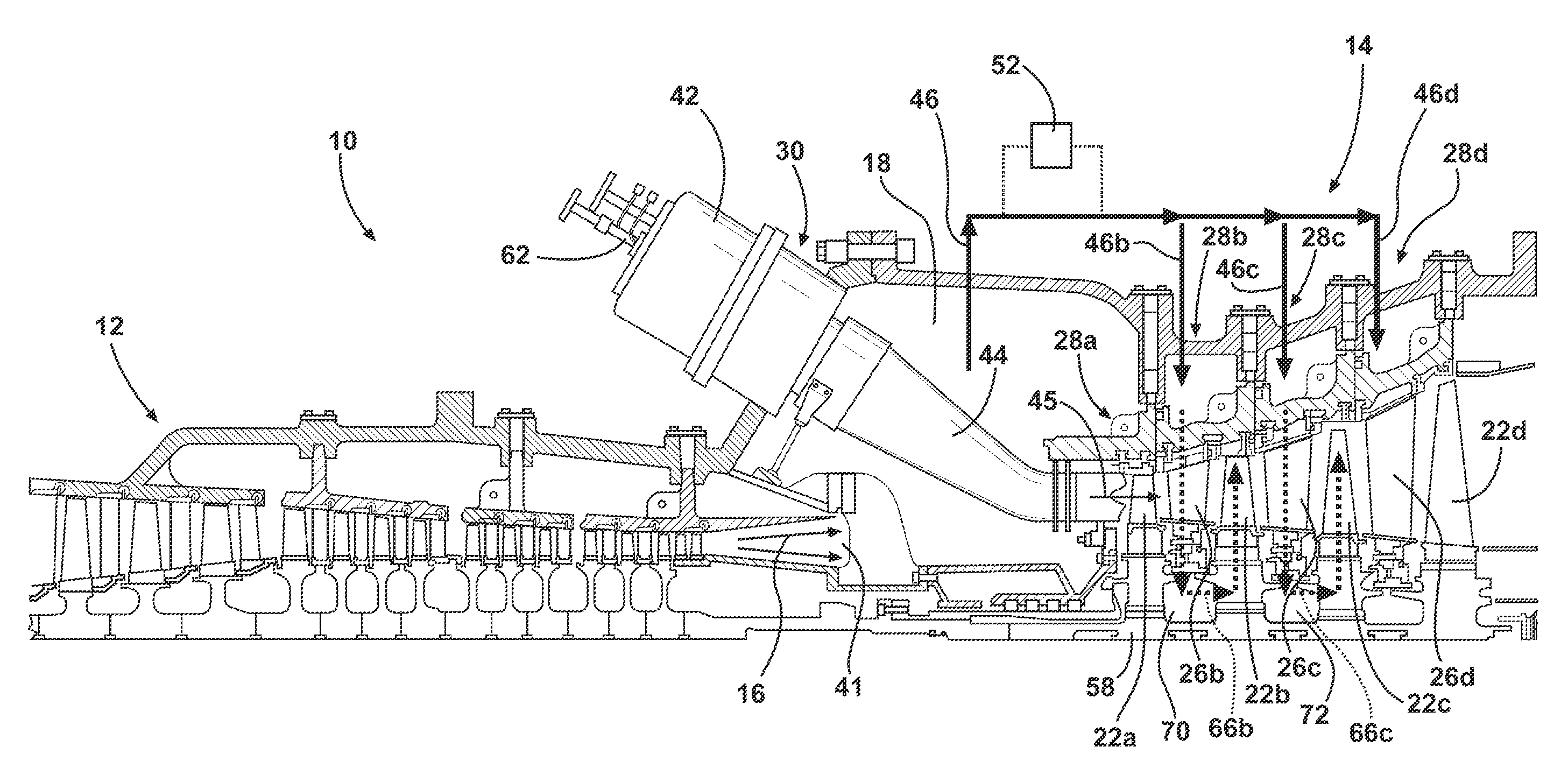
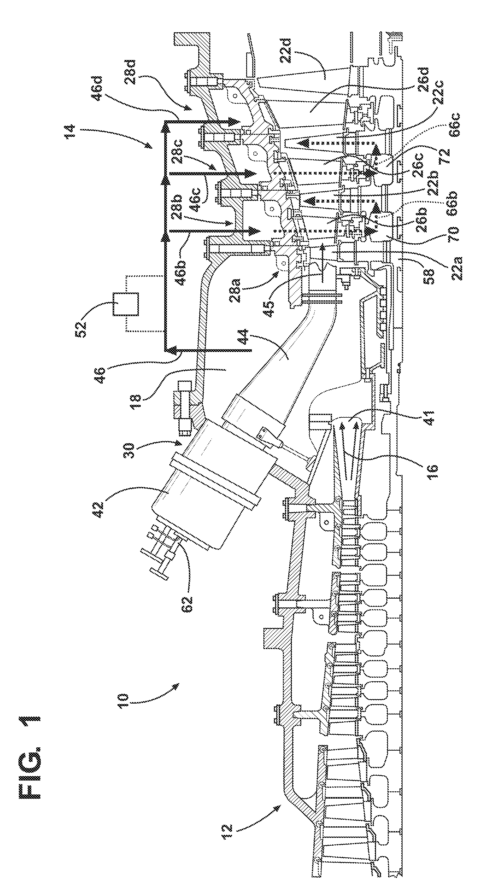
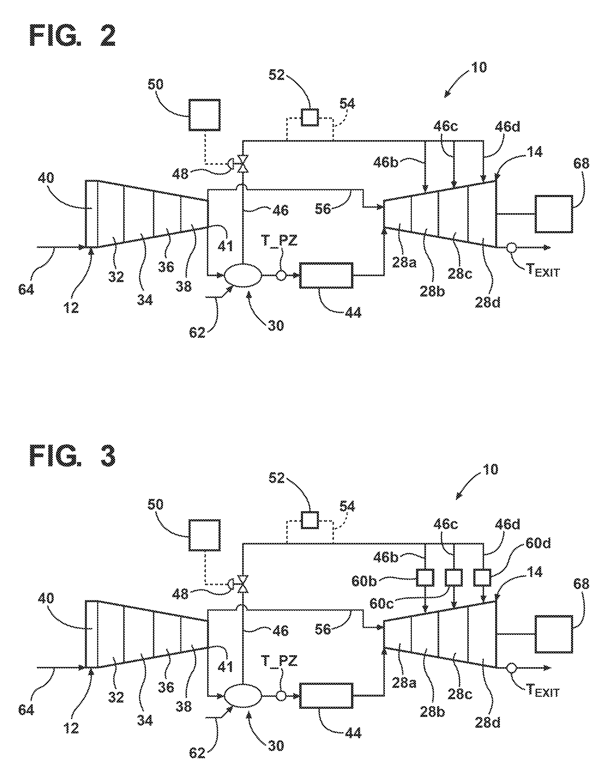
[0008]In accordance with one aspect of the invention, a turbine engine assembly for a generator is provided. The assembly comprises a turbine engine having a compressor section, a combustor section and a turbine section. The combustor section includes a primary zone temperature (T_PZ) and the turbine engine includes a base load. At least one air bleed line is in communication with the combustor section for receiving bleed air comprising combustor shell air from the combustor section. The at least one air bleed line is also in communication with a second stage of the turbine section and in communication with one or more stages of the turbine section downstream from the second stage for supplying bleed air to the turbine section. At least one valve is provided for controlling air flow through the at least one air bleed line, and a controller is provided for opening the at least one valve to allow bleed air to flow through the at least one air bleed line when an operating load is less than the base load to bypass air exiting the compressor section around a combustor in the combustor section and effect a flow of high pressure combustor shell air to the stages of the turbine section.

Problems solved by technology

Part load operation may result in the production of high levels of carbon monoxide (CO) during combustion.

Method used


Image

  • Cooling of Turbine Components Using Combustor Shell Air
  • Cooling of Turbine Components Using Combustor Shell Air
  • Cooling of Turbine Components Using Combustor Shell Air

Examples


Embodiment Construction

[0017]In the following detailed description of the preferred embodiment, reference is made to the accompanying drawings that form a part hereof, and in which is shown by way of illustration, and not by way of limitation, a specific preferred embodiment in which the invention may be practiced. It is to be understood that other embodiments may be utilized and that changes may be made without departing from the spirit and scope of the present invention.

[0018]Referring initially to FIGS. 1 and 2, embodiments of the invention are directed to a turbine engine assembly 10 having a compressor section 12, a combustor section 30, and a turbine section 14. As is known in the art, the compressor section 12 can have one or more stages such as front stages 32, forward stages 34, middle stages 36, and rear stages 38 (FIG. 2). Also, the compressor section 12 can have inlet guide vanes (IGVs) 40 which can be opened and closed or otherwise adjusted to control the mass flow of air into the compressor ...


PUM


Abstract

A turbine engine assembly for a generator including a turbine engine having a compressor section, a combustor section and a turbine section. An air bleed line is in communication with the combustor section for receiving combustor shell air from the combustor section and conveying the combustor shell air as bleed air to a plurality of stages of the turbine section. Bleed air is controlled to flow through the air bleed line when an operating load of the turbine engine assembly is less than a base load of the engine to bypass air exiting the compressor section around a combustor in the combustor section and effect a flow of high pressure combustor shell air to the stages of the turbine section.

Description

CROSS REFERENCE TO RELATED APPLICATION[0001]This application is A CONTINUATION-IN-PART APPLICATION of and claims priority to U.S. patent application Ser. No. 11 / 784,150, (Attorney Docket No. 2007P03605US), filed on Apr. 5, 2007, entitled “ENGINE BRAKE FOR PART LOAD CO REDUCTION,” the entire disclosure of which is incorporated by reference herein.FIELD OF THE INVENTION[0002]The present invention relates generally to turbine engines and, more particularly, to cooling of turbine parts during low load operation of a turbine.BACKGROUND OF THE INVENTION[0003]Turbine engines, such as single shaft industrial gas turbines, are designed to operate at a constant design turbine inlet temperature under any ambient air temperature (i.e., the compressor inlet temperature). This design turbine inlet temperature allows the engine to produce maximum possible power, known as base load. Any reduction from the maximum possible base load power is referred to as part load operation. In other words, part l...

Claims


Application Information

Patent Timeline
Patent Type & Authority Applications(United States)
IPC IPC(8): F02C6/08F02C6/04H02K7/18
CPCF01D9/023F02C3/13F02C6/08F05D2260/20F02C7/185F02C9/18F05D2270/08F02C7/12
Inventor FOUST, ADAM M.NORDLUND, RAYMOND S.CHHABRA, NITINLITTLE, DAVID A.
Owner SIEMENS ENERGY INC
Learn More