
Motor and electric power supply control apparatus for the motor

Inactive Publication Date: 2010-07-08
TOYOTA JIDOSHA KK
View PDF13 Cites 8 Cited by
  • Summary
  • Abstract
  • Description
  • Claims
  • Application Information

AI Technical Summary

Benefits of technology

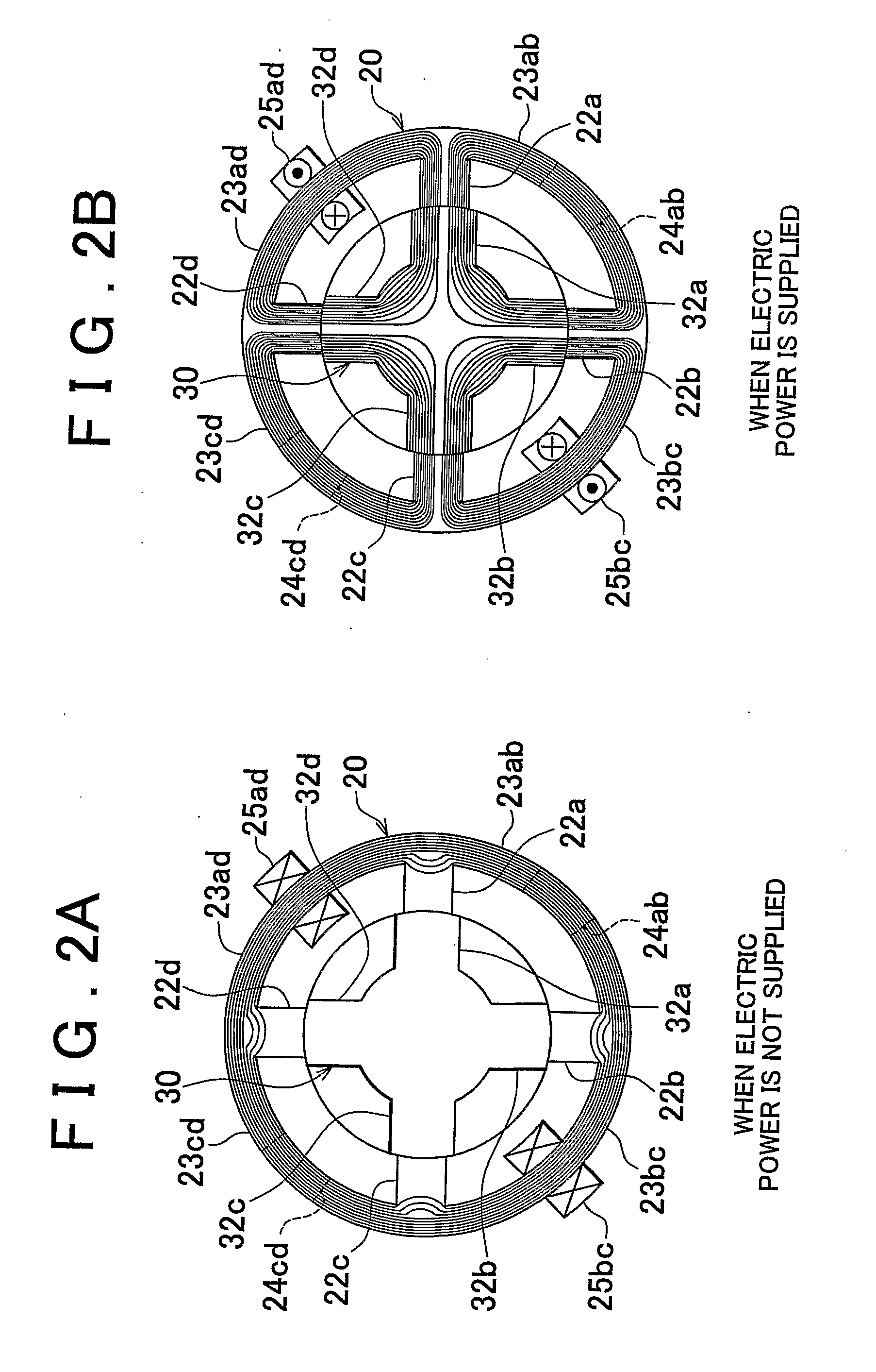
[0009]The invention suppresses torque fluctuations due to cogging torque, etc. that occur when electric power is not supplied to a motor.

Problems solved by technology

However, if the motor produces higher power, motor loss torque, cogging torque, and motor inertia (system inertia) increase in proportion with the increase in the power produced by the motor.
As a result, the steering feel felt by a driver deteriorates.
However, motor loss torque, which occurs when electric power is not supplied to the motor, may cause the deterioration of the steering feel, for example, the driver's steering wheel to turn in an unintentional direction, because feed-back control cannot be performed when electric power is not supplied to the motor.
Cogging torque is also caused when electric power is not supplied to the motor.
Accordingly, the cogging torque also causes deterioration of the steering feel, because feed-back control cannot be performed when electric power is not supplied to the motor.
In addition, such motor loss torque and cogging torque increase in proportion to the output from the motor.
This hampers increases in the motor efficiency and power output from the motor.
In addition, a high-powered motor requires a large number of magnetic circuits in a rotor and a stator.
However, it is not possible to perform complete compensation due to a time constant of the motor or performance of the sensor.
However, if the inertia is large, the inertia will affect the steering feel.
Accordingly, the cogging torque is not appropriately reduced.
As a result, even if such a motor is used in an electric power steering system, the steering feel does not improve.

Method used


Image

  • Motor and electric power supply control apparatus for the motor
  • Motor and electric power supply control apparatus for the motor
  • Motor and electric power supply control apparatus for the motor

Examples


Embodiment Construction

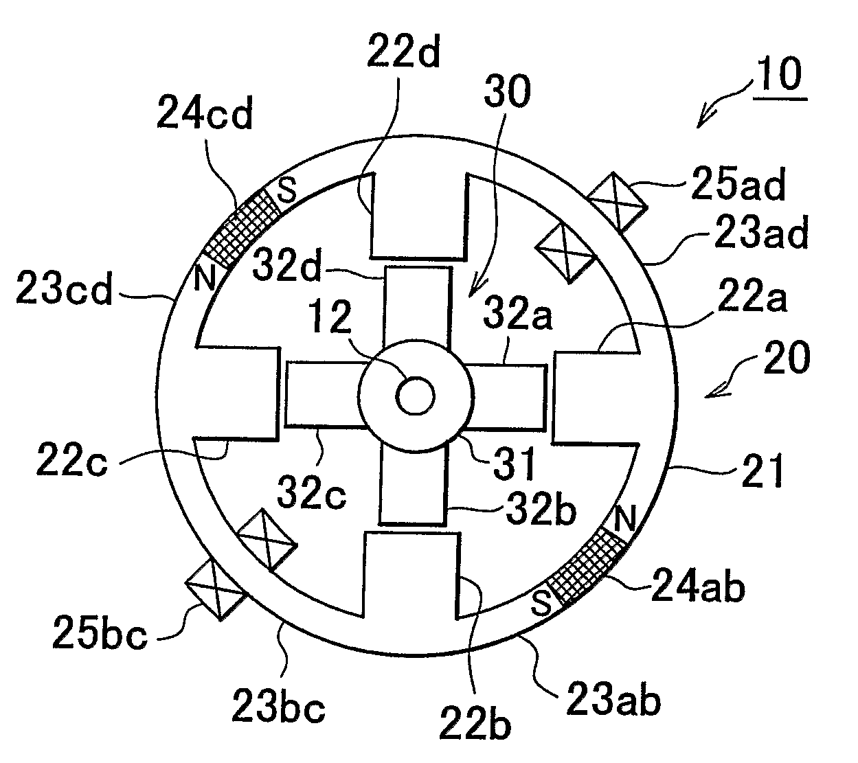
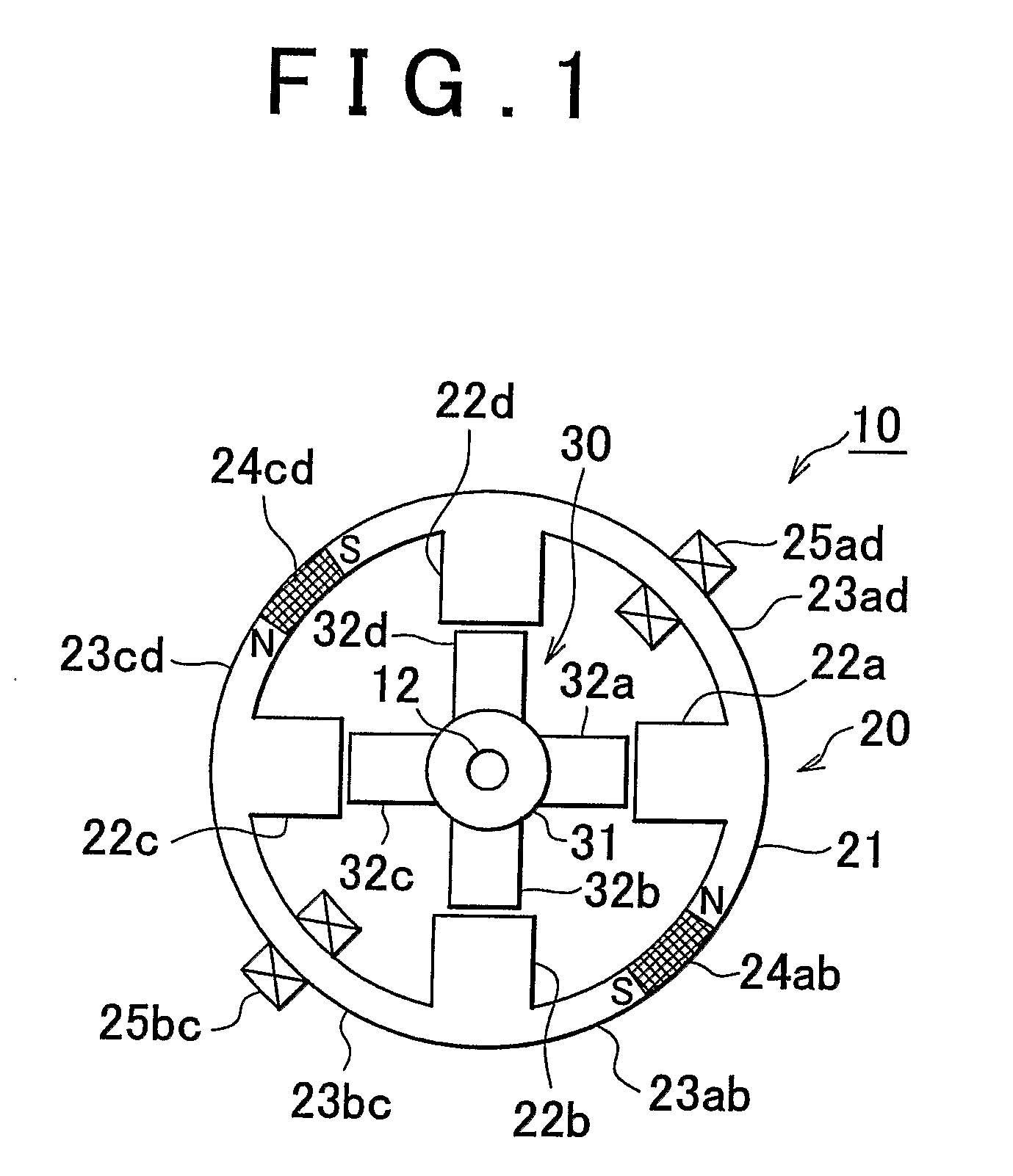
[0048]Hereafter, a motor and an electric power supply control apparatus for the motor according to an embodiment of the invention will be described with reference to the accompanying drawings. As shown in FIG. 3, a motor 1 according to the embodiment of the invention is formed by connecting three base modules 10 (a first base module 10A, a second base module 10B, and a third base module 10C: these base modules will be collectively referred to as the base modules 10) to each other in the axial direction. The motor 1 is used as a drive unit for an electric power steering system which will be described later in detail. First, the base modules 10 will be described. FIG. 1 shows the base module 10 that forms the motor 1 according to the embodiment of the invention. The base module 10 includes a stator 20 fixed to a motor casing 11, and a rotor 30 that is arranged in the stator 20 so as to be able to rotate using a shaft 12 as the rotating shaft.

[0049]The stator 20 is formed of a hollow c...


PUM


Abstract

In a ring body of a stator, permanent magnets are arranged in alternate inter-pole magnetic path portions located between an even number of stator poles so that magnetic fields pointing in the circumferential direction of the ring body are generated. Coils are wound around alternate inter-pole magnetic path portions where permanent magnets are not provided so that magnetic fields that oppose the magnetic fields generated by the permanent magnets are generated. When electric power is not supplied to the coils, a ring-shaped magnetic circuit is formed by the permanent magnets, and therefore, magnetic flux does not leak to a rotor. When electric power is supplied to the coils, the magnetic flux of the magnetic fields of the permanent magnets and that of the coils combine with each other and flow from the stator poles to rotor poles of the rotor, whereby strong attraction force is obtained.

Description

BACKGROUND OF THE INVENTION[0001]1. Field of the Invention[0002]The invention relates to a motor that uses attraction force generated by a permanent magnet, and an electric power supply control apparatus for the motor.[0003]2. Description of the Related Art[0004]In an electric power steering system that steers the steering wheels of a vehicle, for example, a surface mounted permanent-magnet motor (SPM motor) is used as the drive unit. In recent years, the demands for more efficient and higher-power electric power steering systems have been growing. However, if the motor produces higher power, motor loss torque, cogging torque, and motor inertia (system inertia) increase in proportion with the increase in the power produced by the motor. As a result, the steering feel felt by a driver deteriorates.[0005]Although fluctuations in motor torque affect the steering feel, such torque fluctuations may be controlled by controlling the current supplied to the motor in a feedback manner. Howev...

Claims


Application Information

Patent Timeline
IPC IPC(8): B62D5/04H02K37/04H02P6/14H02K1/12H02P25/08
CPCH02K21/44H02K1/14H02K1/185H02K1/22H02P25/08
Inventor YAMASHITA, MASAHARU
Owner TOYOTA JIDOSHA KK
Learn More