Communication method, wireless communication system, transmitter, and receiver

a communication method and wireless communication technology, applied in the field of communication methods, wireless communication systems, transmitters and receivers, can solve the problems of shortening the control channel, inability to effectively use techniques, and accelerating changes in channel quality in a time-dependent direction, so as to avoid increase in circuit size and process delay, and enhance flexibility in allocating resource blocks for sub-sampling transmission

Active Publication Date: 2010-07-01
MITSUBISHI ELECTRIC CORP
View PDF5 Cites 7 Cited by
  • Summary
  • Abstract
  • Description
  • Claims
  • Application Information

AI Technical Summary

Benefits of technology

The present invention relates to a communication method and system for LTE wireless networks. More specifically, it focuses on the allocation of resources in a wireless network where Localized transmission and Distributed transmission are mixed. The invention provides a method for making a notification about the allocation of resource blocks using a bit map, which allows for efficient allocation of resources and reduces the need for control channels. The invention also takes into account the correlation between resource blocks to optimize the use of system resources. Overall, the invention improves the efficiency and effectiveness of resource allocation in wireless networks.

Problems solved by technology

However, as explained above, since 100 resource blocks are present at maximum in LTE, notification to each terminal by using a bit map of 100 bits leads to a shortage of control channels.
On the other hand, although the Localized transmission mentioned above is an effective technique when the traveling speed of the terminal is slow, it cannot be much an effective technique when the traveling speed is fast.
For example, since reporting the channel quality and scheduling require a certain processing time, when the traveling speed is fast, changes of the channel quality in a direction of time is quickened, and therefore the contents of the report of the channel quality may possibly be obsolete at the time of actual data transmission.
Also, in this Sub-sampling transmission, resource blocks to be allocated to one terminal have to be selected from the same subset, and allocating resource blocks from different subsets to one terminal is not allowed.

Method used


Image

  • Communication method, wireless communication system, transmitter, and receiver
  • Communication method, wireless communication system, transmitter, and receiver
  • Communication method, wireless communication system, transmitter, and receiver

Examples


first embodiment

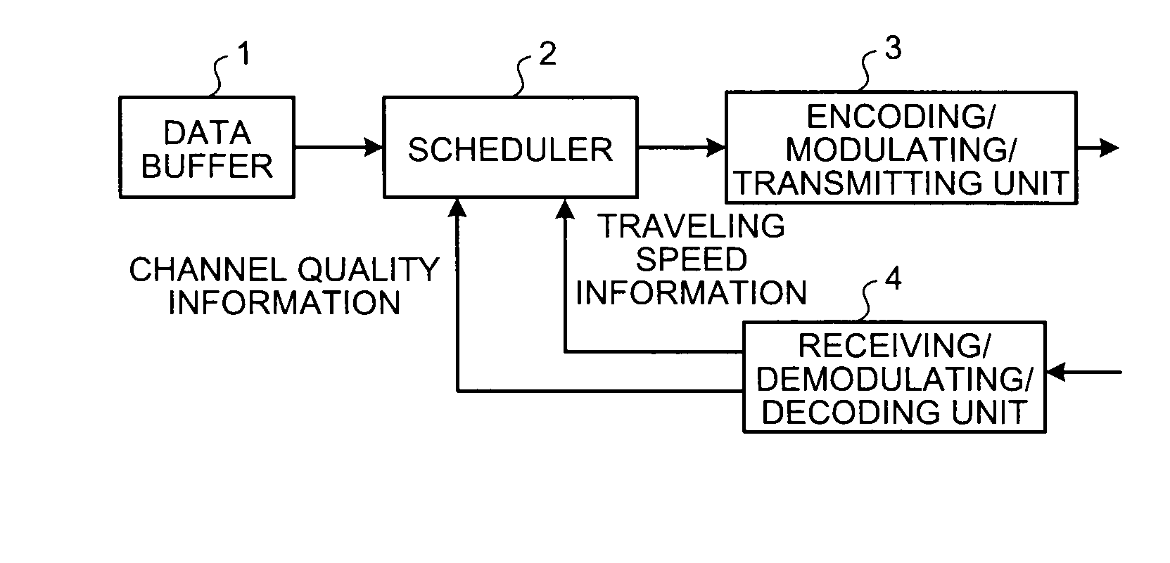
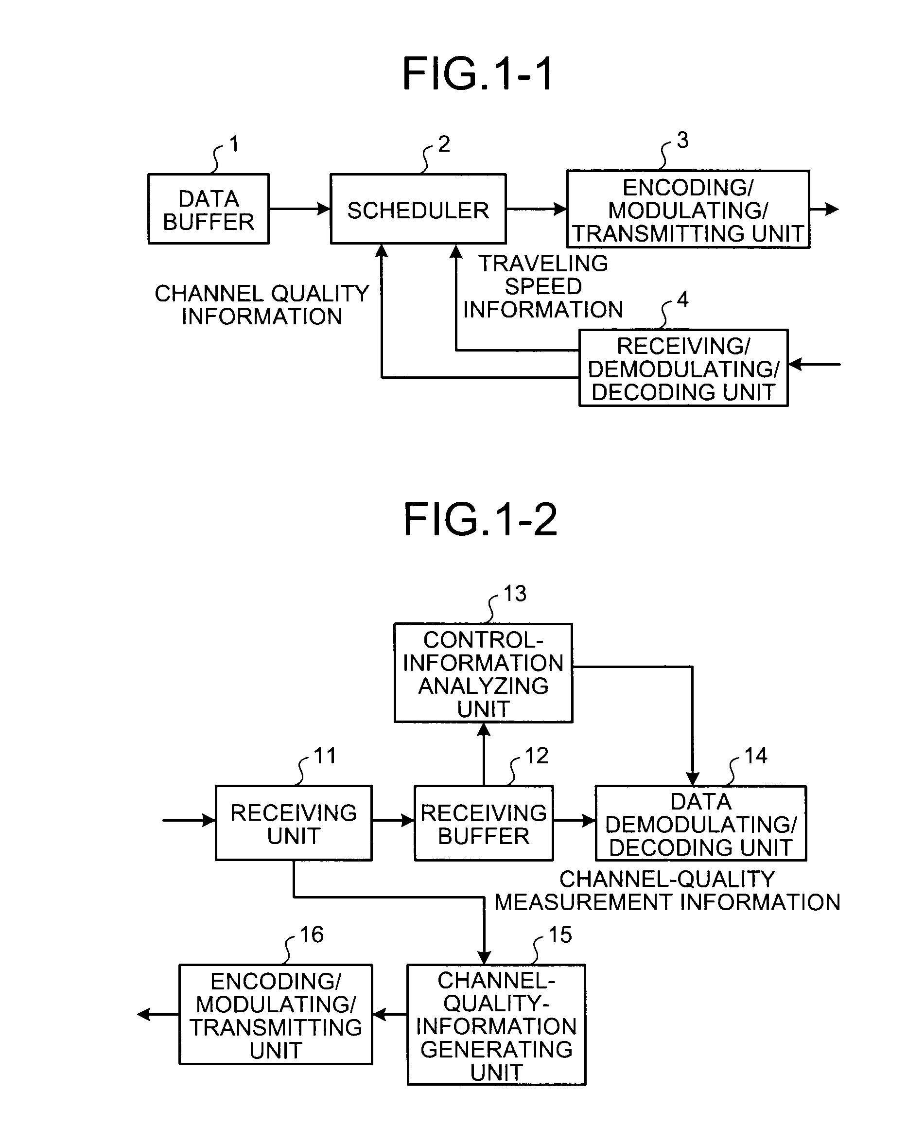
[0063]FIG. 1-1 is a diagram depicting an example of structure of a base station operating as a transmitter for achieving the communication method according to the present invention. This base station is assumed to be configured to include a data buffer 1, a scheduler 2, a coding / modulating / transmitting unit 3, and a receiving / demodulating / decoding unit 4. Also, FIG. 1-2 is a diagram depicting an example of structure of a terminal operating as a receiver for achieving the communication method according to the present invention. This terminal is assumed to be configured to include a receiving unit 11, a receiving buffer 12, a control-information analyzing unit 13, a data demodulating / decoding unit 14, a channel-quality-information generating unit 15, and an encoding / modulating / transmitting unit 16. Furthermore, in the present embodiment, by way of example, it is assumed that the base station depicted in FIG. 1-1 above and a plurality of terminals depicted in FIG. 1-2 configure a wirel...

second embodiment

[0077]Subsequently, a communication method different from that in the first embodiment explained above is explained. Note that the structures of the base station and the terminals are similar to those in the first embodiment explained above. Here, processes different from those in the first embodiment are explained.

[0078]FIGS. 9-1 and 9-2 are diagrams each depicting one example of assigning a scheduling resource number in the second embodiment. In the present embodiment, scheduling resource numbers are provided so that a combination pattern of scheduling resources when aggregation in Localized transmission is performed and resource blocks for Distributed transmission is repeated with a specific periodicity in a frequency direction. For example, in FIG. 9-1, the combination pattern mentioned above corresponding to resource blocks (0)-(4) is repeated for resource blocks (5)-(9), resource blocks (10)-(14), . . . , thereby providing a scheduling resource number for each scheduling resou...

third embodiment

[0087]Subsequently, a communication method different from those in the first embodiment and the second embodiment explained above is explained. Note that the structures of the base station and the terminals are similar to those in the first embodiment explained above. Here, processes different from those in the first and second embodiments are explained.

[0088]FIGS. 12 and 13 are diagrams each depicting one example of assigning scheduling resource numbers in the third embodiment. In the present embodiment, provision of scheduling resource numbers when aggregation is performed is performed on all resource blocks. Also, the process of providing scheduling resource numbers in the present embodiment does not depend on the number of resource blocks for Distributed transmission: N_DPRB. It is predicated herein that notification about N_DPRB is allowed as control information overhead. It is also predicated that resource blocks as many as the number of N_DPRB are not used in Localized transm...


PUM


Abstract

In a wireless communication system where data transmission is performed between a base station and terminals, the base station individually generates, for each terminal, a bit map indicative of scheduling resource numbers to be allocated to terminals to which Localized transmission is applied, based on a resource-number mapping rule defined by providing individual resource block numbers to all resource blocks, taking resource block numbers of resource blocks for Distributed transmission as fixed values, and providing individual scheduling resource numbers to remaining resource blocks for Localized transmission except the resource blocks for Distributed transmission for each of scheduling resources corresponding to the number of aggregation.

Description

TECHNICAL FIELD[0001]The present invention relates to a communication method, wireless communication system, and transmitter and receiver that configure the system when Localized transmission and Distributed transmission are mixed in the same sub-frame.BACKGROUND ART[0002]Currently in 3GPP, under the name of LTE (Long Term Evolution), a wireless system adopting a new wireless technique has been studied. In this wireless system, a plurality of data channel resources are defined on a frequency axis to measure the state of quality of each channel and, based on the measurement results, a data channel resource for use in communication is determined. And, a notification about the data channel resource determined therein is made as allocation information by using a control channel to each terminal configuring the system mentioned above.[0003]Also, in a downstream (base station→terminal) frame studied as LTE, a control channel and a data channel are disposed in one sub-frame, and resource a...

Claims


Application Information

Patent Timeline
Patent Type & Authority Applications(United States)
IPC IPC(8): H04B7/00H04J1/00H04J11/00H04W72/54
CPCH04L5/0037H04L5/0044H04L5/0053H04L5/0094H04L47/824H04L47/828H04W72/1263H04L5/0007H04L5/0039H04L5/0041H04L5/0091H04L27/2601H04W72/04H04W88/10H04L47/70H04L47/83
Inventor FUKUI, NORIYUKITANI, SHIGENORI
Owner MITSUBISHI ELECTRIC CORP
Why Eureka
Try Eureka