
System and method for acquiring image data

a technology of image data and acquisition method, applied in the field of system and method for acquiring image data, can solve the problems of placing stringent and demanding requirements, and achieve the effects of low false alarm rate, less expansive, and good detection ra

Inactive Publication Date: 2010-07-01
KONINKLIJKE PHILIPS ELECTRONICS NV
View PDF6 Cites 5 Cited by
  • Summary
  • Abstract
  • Description
  • Claims
  • Application Information

AI Technical Summary

Benefits of technology

[0012]The using of at least one scanning unit which is able to follow a bag may increase the throughput in order to fulfil system requirements of an increased number of bags per hour, which requirements may not allow the stopping of the bag for further inspection of false alarms, but may instead requires so-called “on the fly” alarm resolution. By using a three-dimensional imaging system according to the exemplary embodiment the known baggage inspection may be simplified. In particular, the throughput may be increased due to the fact that the baggage may not be stopped during scanning while still a longer period of scanning may be performed than in the case of conventional system in which the scanning unit, i.e. the direction of the radiation emitted by a radiation source of the scanning unit, does not follow the baggage in its linear movement.
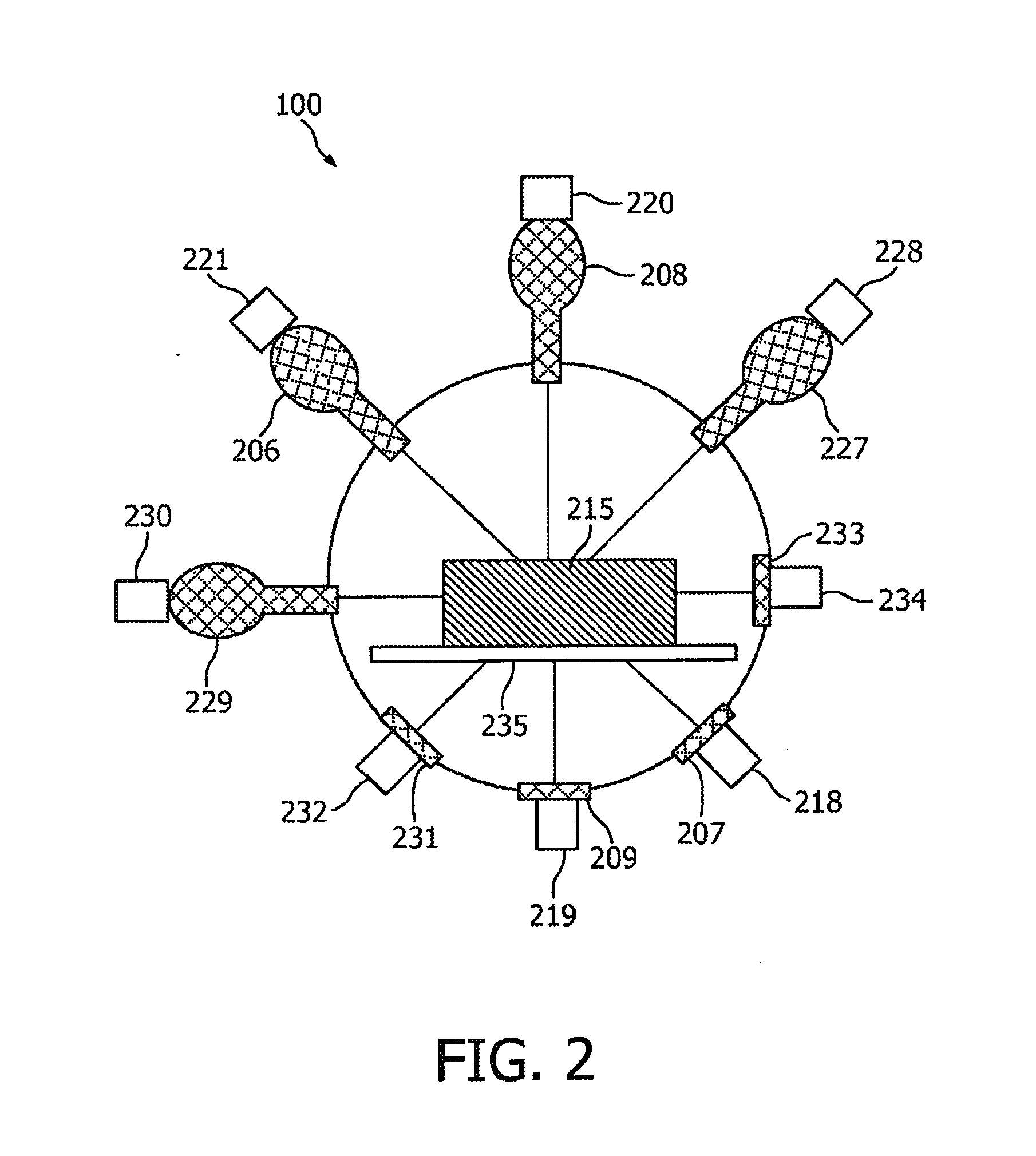
[0047]In an embodiment a diffractive scanning unit may be introduced downstream from a CT-scanner, which diffractive scanning unit generates a scanning pencil beam pointed and moved such that it intersects with a region-of-interest (ROI) inside a bag during the entire movement of the bag through the diffractive sub system. On the opposite side of the baggage transport tunnel a scatter detector is positioned, which records the scattered radiation. The scatter detector may either be large and thus does not need to be moved for scanning or it may be a smaller one and thus needs to be moved during scanning. Since the bag is moved during scanning, only the ROI may be permanently in the beam whereas surrounding material may only be in the beam for a short time and thus may not produce a significantly structured background. Reconstruction methods based on tomosynthesis may be applied to possibly get an even better picture of the scatter properties of the ROI. As an additional feature, a secondary collimator may be placed in front of the scatter detector and may be moved and rotated such that the viewing direction of the detector always intersects with the primary beam at the ROI within the object.

Problems solved by technology

Although Coherent Scattering Computer Tomography (CSCT) is a very promising technique, problems exist when applying it to the field of baggage inspection.
For example, such applications place stringent and demanding requirements in relation to throughput, dark alarms and findings.

Method used


Image

  • System and method for acquiring image data
  • System and method for acquiring image data
  • System and method for acquiring image data

Examples


Embodiment Construction

[0055]FIG. 1 shows a simplified schematic side-view of a geometry for a Computer Tomography system 100 according to an embodiment. The CT system 100 comprises a first scanning unit 101 or pre-scanning unit and a second region 102. The first scanning unit 101 comprises a first X-ray tube 103 and a first detection unit 104 which are arranged opposite to one another with respect to an object under examination, e.g. a bag 114. According to the shown embodiment the first scanning unit is formed as a fast standard Computer Tomography scanning unit, e.g. a cone-beam CT unit, and comprises a gantry 105 on which the first scanning unit 101 is mounted, i.e. the first X-ray tube 103 and the first detection unit 104, in a way that they can rotate around the bag 114. The second region 102 comprises a first second scanning unit which is schematically shown having a first second X-ray tube 106 and a first second detection unit 107, which is formed as a diffraction detector. Furthermore, the second...


PUM


Abstract

According to an exemplary embodiment an imaging system (100) for examining an object under examination comprises a scanning unit, wherein the scanning unit comprises a radiation source (106, 108), and a detection unit (107, 109), wherein the scanning unit is adapted to emit a radiation beam (123), which radiation beam follows a linear movement of the object under examination such that a predetermined region of the object under examination is scanned while the object under examination moves.

Description

FIELD OF THE INVENTION[0001]The invention relates to a system and a method for acquiring image data, a computer readable medium and a computer program. In particular, the invention relates to a cone-beam Computer Tomography system for baggage inspection having a high baggage throughput.BACKGROUND OF THE INVENTION[0002]Systems for producing an image of a physical object are widespread in several technical fields. One area of particular commercial interest is that of fast baggage scanners that can be used in a number of instances, but are often particularly used to scan airline baggage. Another area of particular commercial interest is in the field of medical scanners. Beside the already known and widespread Computer Tomography (CT) devices a relatively new field of so-called Scattering Computer Tomography devices as well as of diffractive scanning units is developing.[0003]For medical use as well as for baggage inspection, attenuation of transmitted radiation, not scattering, is gene...

Claims


Application Information

Patent Timeline
IPC IPC(8): G06K9/00
CPCG01T1/1644G01V5/0025G01V5/005G01V5/226G01V5/222
Inventor SCHLOMKA, JENS-PETERTHRAN, AXEL
Owner KONINKLIJKE PHILIPS ELECTRONICS NV
Learn More