
Friction weld vibration quality monitoring system

a vibration quality monitoring and vibration technology, applied in the field of friction welding system and method, can solve the problems of insufficient reliability, high cost, and high cost of systems and equipment for damping, so as to reduce or eliminate the need, and improve the quality of welds

Inactive Publication Date: 2010-07-01
GENERAL ELECTRIC CO
View PDF3 Cites 11 Cited by
  • Summary
  • Abstract
  • Description
  • Claims
  • Application Information

AI Technical Summary

Benefits of technology

[0008]One advantage of the present disclosure includes reduction or elimination of expensive processing and equipment of friction welded articles.
[0009]Another advantage of the present disclosure includes reduction or elimination of the need for expensive and unreliable equipment for vibration damping.
[0010]Another advantage of the present disclosure is improved weld quality and improved process control allowing for greater process efficiency.

Problems solved by technology

Operation of the inertial welding machine may result in vibration.
The vibration energy can cause damage to the workpieces and tooling that can be identified by inspection after the weld process is complete.
Such inspection adds complexity and cost to the process.
However, systems and equipment for damping are expensive and are not fully reliable.

Method used


Image

  • Friction weld vibration quality monitoring system
  • Friction weld vibration quality monitoring system
  • Friction weld vibration quality monitoring system

Examples


Embodiment Construction

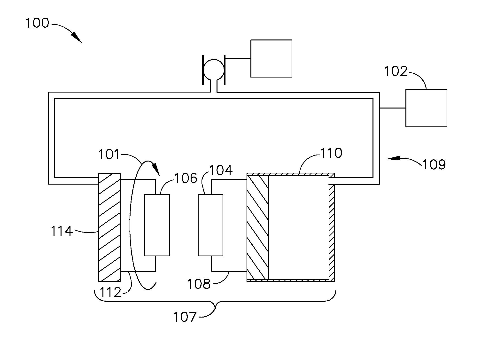
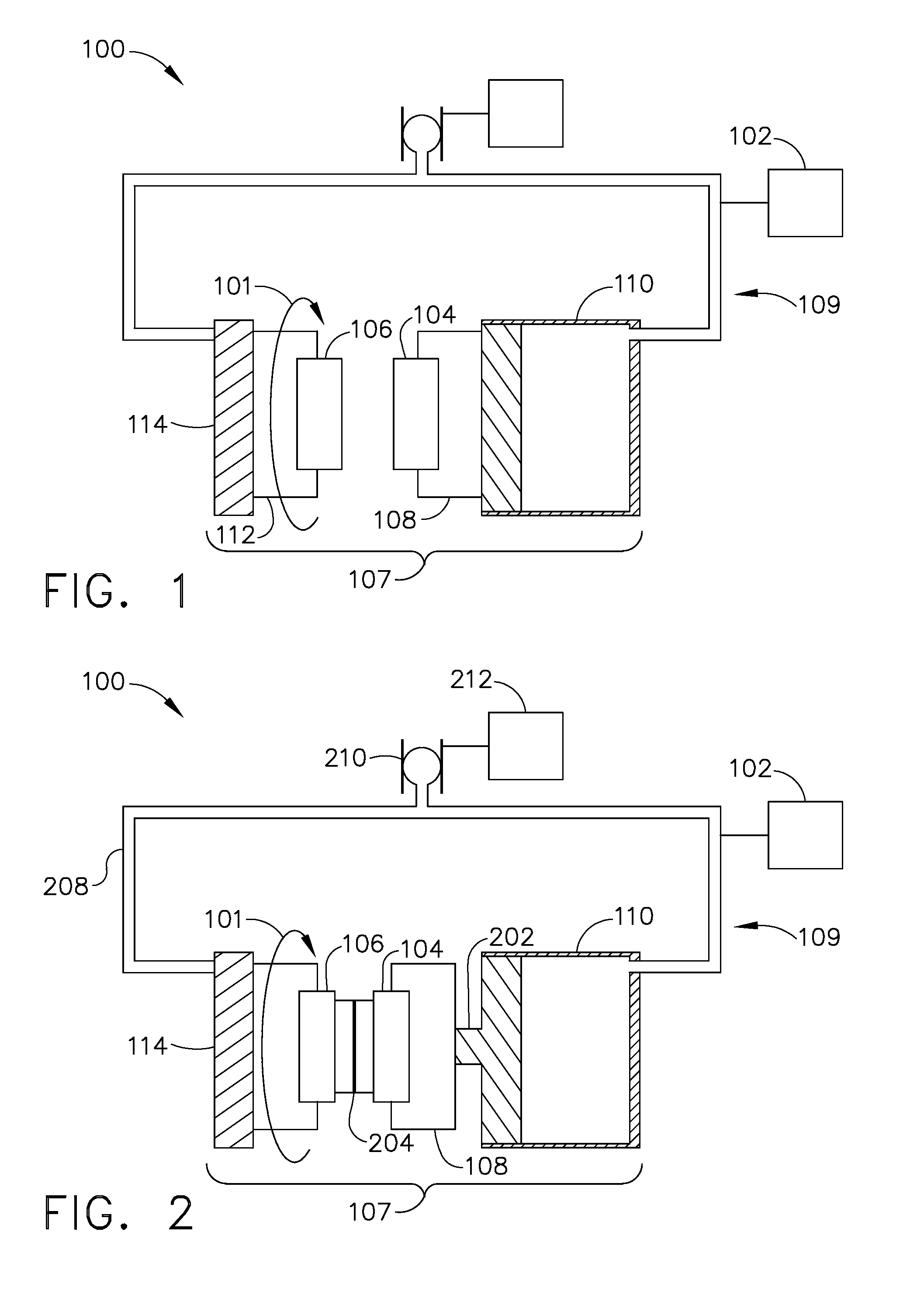
[0017]FIG. 1 shows a friction welding system 100. The friction welding system 100 may include an inertial welding arrangement 107, a force providing mechanism 109, and a sensor 102. Inertial welding arrangement 107 is configured to impart a kinetic friction between at least one surface of a first workpiece 104 and at least one surface of a second workpiece 106. Welding arrangement 107 can include a first securing mechanism 108 arranged and disposed for receiving and securing first workpiece 104. As shown, first workpiece 104 is detachably secured by first securing mechanism 108, which prevents rotation of first workpiece 104. First securing mechanism 108 can be attached to or integral with a hydraulic cylinder 110. Welding arrangement 107 can further include a second securing mechanism 112 arranged and disposed to receive and secure second workpiece 106. As shown, second workpiece 106 can be secured by second securing mechanism 112, while permitting second workpiece 106 to rotate (s...


PUM

PropertyMeasurementUnit
Forceaaaaaaaaaa
Pressureaaaaaaaaaa
Frequencyaaaaaaaaaa

Abstract

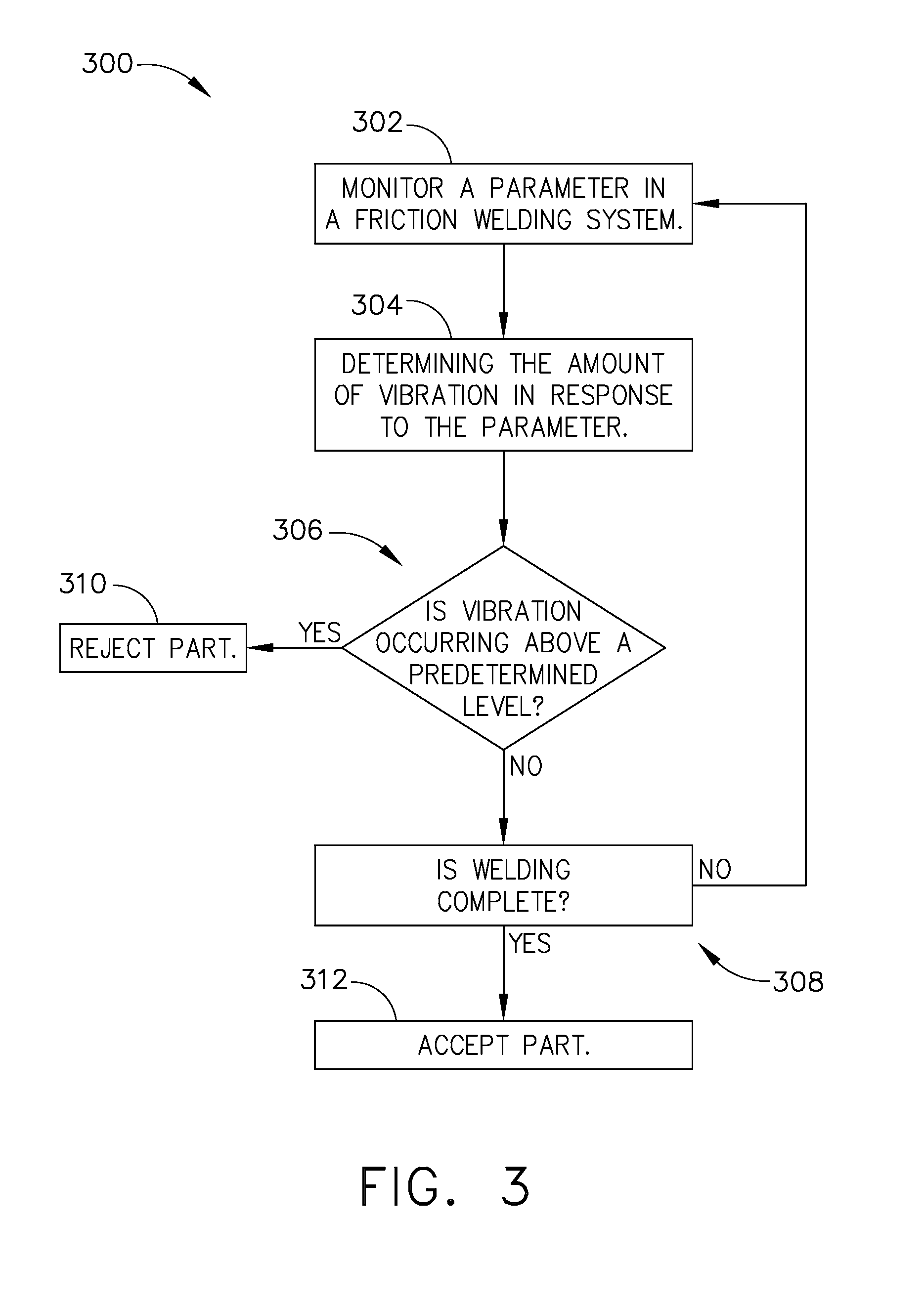
Friction welding systems and methods including a welding arrangement configured to impart kinetic friction between at least one surface of a first workpiece and at least one surface of a second workpiece to form a weld, a force providing mechanism arranged and disposed for applying a force to one or both of the first workpiece and the second workpiece, and a sensor arranged and disposed to measure a parameter of the welding arrangement, wherein an amount of vibration is determinable from the measured parameter.

Description

FIELD[0001]The present disclosure is directed to a system and method for friction welding. In particular, the present disclosure relates to monitoring vibration during friction welding.BACKGROUND[0002]A friction welding system, specifically an inertia or inertial welding system, utilizes friction between surfaces to be joined to produce heat that bonds a first workpiece and a second workpiece together. The two workpieces to be bonded are mounted on an inertial welding machine. In one type of system, the first workpiece is held stationary, while the second workpiece is rotated rapidly on a spindle attached to a fly wheel. When the fly wheel reaches a predetermined speed, the fly wheel is disengaged and pressure is applied to the first workpiece to urge the first workpiece against the second workpiece. Kinetic friction between the first workpiece and the second workpiece generates heat sufficient to form a bond between the first workpiece and the second workpiece.[0003]The first workp...

Claims


Application Information

Patent Timeline
IPC IPC(8): B23K20/12
CPCB23K20/12B23K20/121
Inventor GROOMS, JAMESCARRIER, CHARLES WILLIAM
Owner GENERAL ELECTRIC CO
Learn More