
Injection Molding Material Containing Starch and Plant Protein

a technology of injection molding material and starch, which is applied in the direction of synthetic resin layered products, domestic objects, woodworking apparatus, etc., can solve the problems of increasing the time and cost involved in molding operation, affecting the quality of injection molding, and often forming synthetic polymers

Inactive Publication Date: 2010-06-24
KIMBERLY-CLARK WORLDWIDE INC
View PDF100 Cites 33 Cited by
  • Summary
  • Abstract
  • Description
  • Claims
  • Application Information

AI Technical Summary

Problems solved by technology

One problem associated with such containers, however, is that the molding material is often formed from a synthetic polymer (e.g., polypropylene or HDPE) that is not renewable (e.g., directly obtained or derived from a plant) or biodegradable.
The use of biodegradable and renewable polymers in the injection molding material is likewise problematic due to the difficulty involved with thermally processing such polymers.
Further, when attempting to use biodegradable polymers, it is also generally necessary to use a different molding tool due to the differences in shrinkage properties between such polymers and conventional synthetic polymers.
Unfortunately, the need to change molding tools increases the time and costs involved with the molding operation.

Method used


Image

  • Injection Molding Material Containing Starch and Plant Protein
  • Injection Molding Material Containing Starch and Plant Protein
  • Injection Molding Material Containing Starch and Plant Protein

Examples


example 1

[0039]100 wt. % Pro-Cote® 4200 (DuPont) was initially added to a K-Tron feeder (K-Tron America, Pitman, N.J.) that fed the materials into a ZSK-30 co-rotating, twin screw extruder (Werner and Pfleidere Corporation, Ramsey, N.J.). Pro-Cote® 4200 is a soy protein having a weight average molecular weight of about 150,000 to 200,000 Daltons. The extruder diameter was 30 mm and the length of the screws was up to 1328 mm. The extruder has 14 barrels, numbered consecutively 1 to 14 from the feed hopper to the die. The first barrel received the soy protein at a feed rate of 10 lbs / hr. The temperature profile of zones 1 to 14 of the extruder was 100-130° C. for each zone. The screw speed was set at 110 rpm to achieve a torque of 40%. The melt temperature was 123° C. Glycerin was pumped into barrel 5 with a pressurized injector connected with an Eldex pump (Napa, Calif.) at a rate of 24 grams per minute to achieve a 30 wt. % concentration. The vent was opened at the end of the extruder to rel...

example 2

[0040]A mixture of 80 wt. % GlucOSOITM 800 (Chemstar, Minneapolis, Minn.) and 20 wt. % Pro-Cote® 4200 (DuPont) was initially formed in a Hobart mixer. Glucosol™ 800 is a modified starch having a weight average molecular weight (determined by GPC) of 2,900,000; polydispersity index of about 28; bulk density of 30˜40 lbs / ft3, and D98 particle size of 140 mesh. The mixture was then added to a K-Tron feeder (K-Tron America, Pitman, N.J.) that fed the materials into a ZSK-30 co-rotating, twin screw extruder (Werner and Pfleidere Corporation, Ramsey, N.J.) as described in Example 1. The first barrel received the mixture at a feed rate of 10 lbs / hr. The temperature profile of zones 1 to 14 of the extruder was 90° C., 110° C., 125° C., 130° C., 130° C., 122° C., and 117° C. The screw speed was set at 150 rpm to achieve a torque of about 60%. The melt temperature was 128° C. to 130° C. Glycerin was pumped into barrel 5 with a pressurized injector connected with an Eldex pump (Napa, Calif.) a...

example 3

[0041]A mixture of 60 wt. % Glucosol™ 800 (Chemstar, Minneapolis, Minn.) and 40 wt. % Pro-Cote® 4200 (DuPont) was initially formed in a Hobart mixer and then added to a K-Tron feeder (K-Tron America, Pitman, N.J.) that fed the materials into a ZSK-30 co-rotating, twin screw extruder (Werner and Pfleidere Corporation, Ramsey, N.J.) as described in Example 1. The first barrel received the mixture at a feed rate of 10 lbs / hr. The temperature profile of zones 1 to 14 of the extruder was 90° C., 110° C., 118° C., 122° C., 122° C., 122° C., and 115° C., The screw speed was set at 150 rpm to achieve a torque of about 60% to 68%. The melt temperature was 124° C. to 127° C. Glycerin was pumped into barrel 5 with a pressurized injector connected with an Eldex pump (Napa, Calif.) at a rate of 24 grams per minute to achieve a 30 wt. % concentration. The vent was opened at the end of the extruder to release moisture. A die was employed to form strands that had 2 openings of 7 mm in diameter, whi...


PUM

PropertyMeasurementUnit
Densityaaaaaaaaaa
Flexural modulusaaaaaaaaaa
Shrinkageaaaaaaaaaa

Abstract

An injection molding material that includes a renewable resin containing a combination of renewable polymers (e.g., starch and plant protein) and a plasticizer is provided. Although such compounds are normally difficult to process into thermoplastics, the present inventors have discovered that injection molding materials may nevertheless be formed by melt blending the renewable resin with a synthetic resin (e.g., polyolefin) while selectively controlling the nature of the resins and their relative concentrations. In this manner, a morphology may be achieved in which the renewable resin is present as a discontinuous phase that is dispersed within a continuous phase of the synthetic resin (e.g., “island-in-the-sea” morphology). The discontinuous and continuous phases may each constitute from about 30 vol. % to about 70 vol. %, and in some embodiments, from about 40 vol. % to about 60 vol. %. With such a morphology, the continuity of the synthetic resin can minimize the aggregate properties of the renewable resin such that the molding material possesses melt properties similar to that of the synthetic resin. Further, this morphology may also minimize the need to use different molding tools as the shrinkage properties of the overall composition may be substantially similar to that of the synthetic resin.

Description

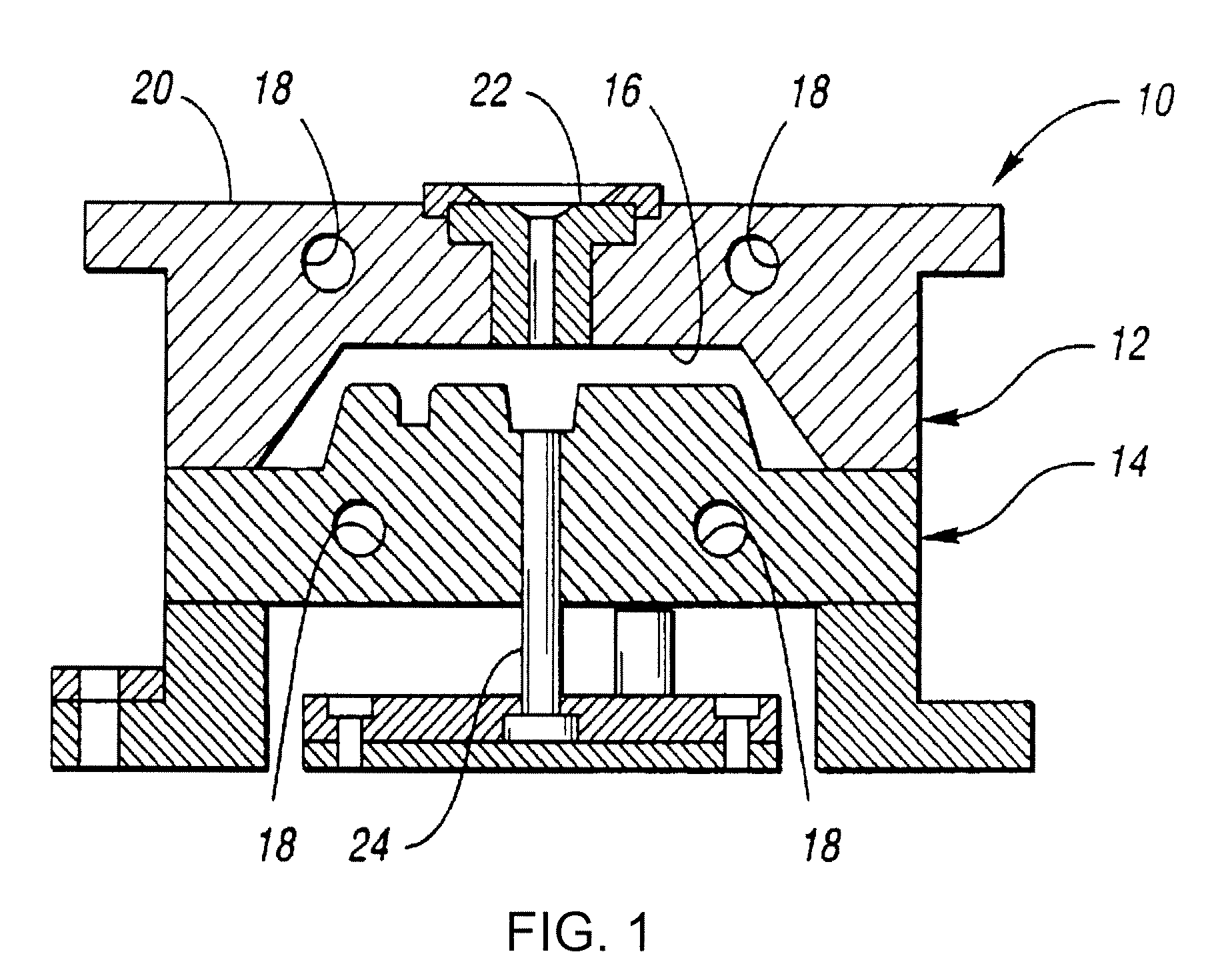
BACKGROUND OF THE INVENTION[0001]Injection molding is commonly used to form plastic articles that are relatively rigid in nature, including containers, medical devices, and so forth. For example, containers for stacks or rolls of pre-moistened wipes are generally formed by injection molding techniques. One problem associated with such containers, however, is that the molding material is often formed from a synthetic polymer (e.g., polypropylene or HDPE) that is not renewable (e.g., directly obtained or derived from a plant) or biodegradable. The use of biodegradable and renewable polymers in the injection molding material is likewise problematic due to the difficulty involved with thermally processing such polymers. Further, when attempting to use biodegradable polymers, it is also generally necessary to use a different molding tool due to the differences in shrinkage properties between such polymers and conventional synthetic polymers. Unfortunately, the need to change molding tool...

Claims


Application Information

Patent Timeline
IPC IPC(8): B32B1/00C08L89/00B29C45/00
CPCB29C45/0001Y10T428/1348B29K2711/00B29K2995/006C08L1/00C08L3/00C08L3/02C08L23/02C08L23/04C08L23/06C08L23/10C08L89/00C08L2205/02B29K2105/16Y10T428/1352C08L2666/06C08L2666/26C08L2207/066
Inventor WANG, JAMES H.WIDEMAN, GREGORY J.SHI, BOFUNK, SARAH A.
Owner KIMBERLY-CLARK WORLDWIDE INC
Learn More