
Hard anodize of cold spray aluminum layer

a technology of hard anodizing and aluminum layer, which is applied in the direction of superimposed coating process, machines/engines, mechanical equipment, etc., can solve the problems of inferior wear resistance of hard anodizing coating, aa 2024 is soft,

Inactive Publication Date: 2010-06-24
UNITED TECH CORP
View PDF22 Cites 32 Cited by
  • Summary
  • Abstract
  • Description
  • Claims
  • Application Information

AI Technical Summary

Benefits of technology

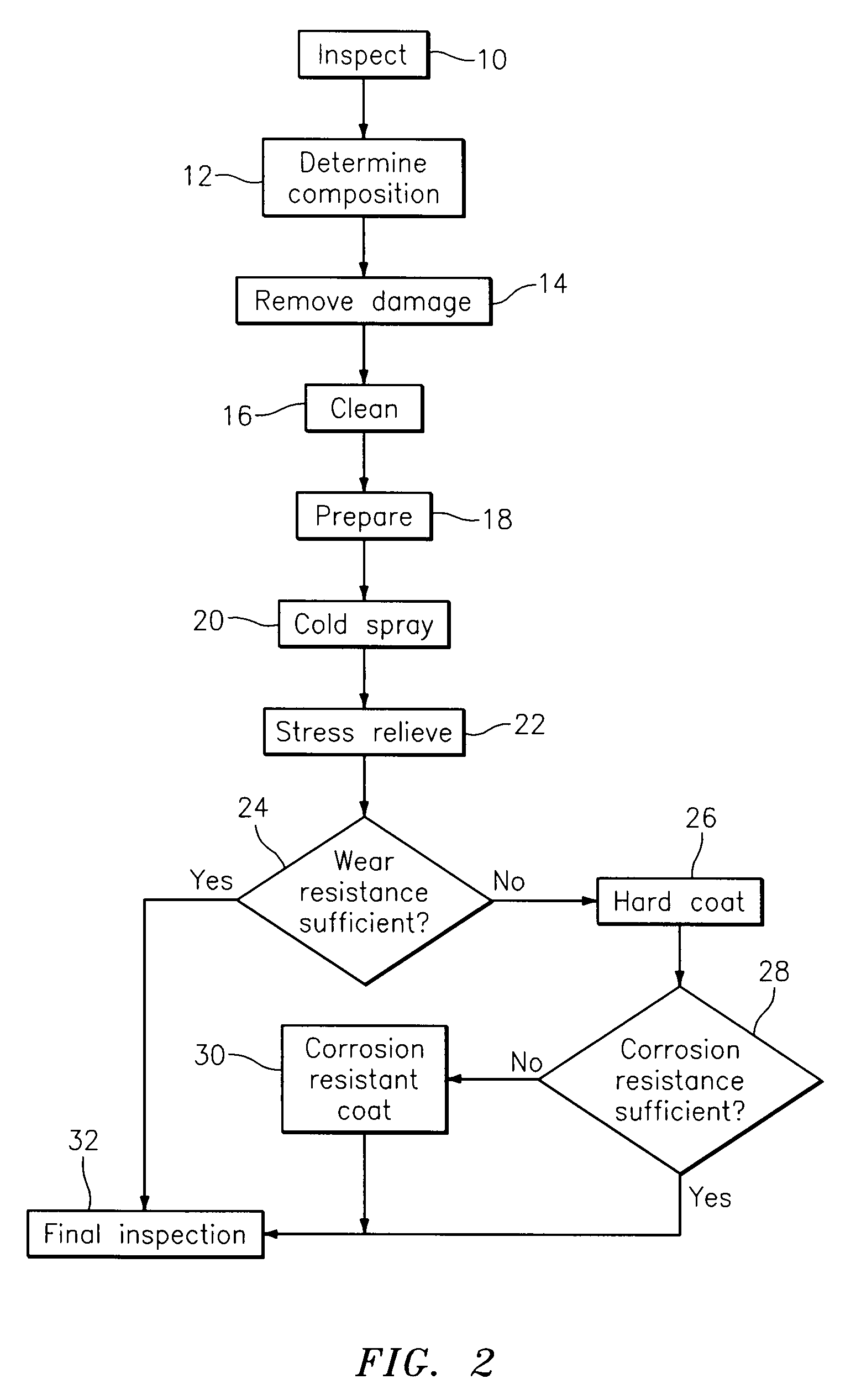
The present patent describes a process for repairing components by depositing a repair material over an affected area on the surface of the component, anodizing the repair material to form a hard anodized coated component, and then contacting the hard anodized coated component with a corrosion resistant sealant solution to form a corrosion resistant sealant coating. The technical effect of this process is that it provides a durable and corrosion-resistant coating on the repaired area of the component, which improves its performance and reliability.

Problems solved by technology

Aluminum alloys such as AA 6061 and AA 2024 are soft and suffer damage via general wear, fretting against steel components, impact, etc.
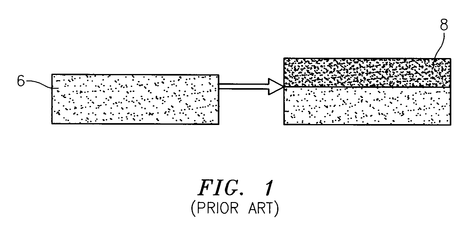
There exist many means to dimensionally restore aluminum alloys; however, wear resistance is inferior to these hard anodic coatings.
Aluminum alloys are susceptible to general corrosion and especially salt (halide) environments and galvanic corrosion during regular service in the field.
And, magnesium alloys, being typically less noble than aluminum alloys, are actually more susceptible to galvanic corrosion.
For example, corrosion damage can be caused from electrical contact with a more noble alloy or by electrolytes in the presence of water or moisture.
There exists a drawback to hard anodizing processes.
Hard anodizing processes consume part of the components' surface.
Magnesium alloys can be hard anodized, but the processes are substantially more difficult and expensive.

Method used


Image

  • Hard anodize of cold spray aluminum layer
  • Hard anodize of cold spray aluminum layer
  • Hard anodize of cold spray aluminum layer

Examples


Embodiment Construction

[0017]Over the last several years, a technique known as cold gas dynamic spraying (“cold spray”) has been developed. This technique is advantageous in that it provides sufficient energy to accelerate particles to high enough velocities such that, upon impact during an initial pass, the particles plastically deform and bond to the surface of the component on which they are being deposited so as to build a relatively dense coating or structural deposit. On subsequent passes, the particles bond to the previously deposited layer. Cold spray does not metallurgically transform the particles from their solid state. The cold spray process has been found to be most useful in effecting repairs of components formed from ductile materials. For example, the cold spray process may be used during the repair of turbine engine components, such as a fan exit inner case or a gearbox, formed from aluminum or magnesium based materials. One such suitable cold spraying process is disclosed in U.S. Pat. Pu...


PUM

PropertyMeasurementUnit
particle sizeaaaaaaaaaa
speedaaaaaaaaaa
particle sizesaaaaaaaaaa

Abstract

A process for repairing components includes the steps of providing a component having an affected area on a surface of a component to be repaired; depositing a repair material over the affected area on the surface of the component so that the repair material plastically deforms without melting and bonds to the affected area upon impact with the affected area and thereby covers the affected area; providing a sulfuric acid based anodizing solution; anodizing a deposited repair material on the surface of said component in the sulfuric acid based anodizing solution; consuming only a portion of the deposited repair material to form a hard anodized coating layer upon the deposited repair material to form a hard anodized coated component; providing a corrosion resistant sealant solution; and contacting a hard anodized coated component with the corrosion resistant sealant solution to form a corrosion resistant sealant coating on the hard anodized coated component.

Description

FIELD OF THE DISCLOSURE[0001]The invention relates to the field of repairing gas turbine components that have experienced corrosion damage and, more particularly, relates to methods that extend component life by reducing or eliminating further corrosion damage which could cause the component to be scrapped.BACKGROUND OF THE DISCLOSURE[0002]Gas turbine engine components, such as fan cases, bleed valves, bleed ducts, clamps, nacelle v-grooves, nacelle track sliders, gearboxes, and the like, are typically constructed of aluminum and magnesium alloys. Aluminum alloys such as AA 6061 and AA 2024 are soft and suffer damage via general wear, fretting against steel components, impact, etc. One method of mitigating wear of aluminum alloys is anodic conversion of the alloy to produce a hard oxide layer on the exposed surface per processes such as AMS 2468 or AMS 2469. There exist many means to dimensionally restore aluminum alloys; however, wear resistance is inferior to these hard anodic coa...

Claims


Application Information

Patent Timeline
Patent Type & Authority Applications(United States)
IPC IPC(8): C25D5/02C23F13/00
CPCC23C24/04C25D11/08C25D11/16C25D11/24C25D11/30C23C28/345F05D2230/31F05D2230/90F05D2300/121C23C28/322F01D5/288
Inventor BOGUE, WILLIAMDEROSA, ROBERT J.LOMASNEY, GARY M.BUNTING, BILLIE W.PARKOS, JR., JOSEPH J.
Owner UNITED TECH CORP
Learn More