Method for producing a plastic foil tube and a related plastic foil tube

a technology of plastic foil and production method, which is applied in the direction of transportation and packaging, other domestic articles, chemistry apparatus and processes, etc., can solve the problems of limited production of foils with a low wall thickness, inability to achieve shape accuracy, and inability to produce certain plastic foils at all. achieve the effect of reducing stresses

Inactive Publication Date: 2010-06-17
AIRBUS OPERATIONS GMBH
View PDF3 Cites 4 Cited by
  • Summary
  • Abstract
  • Description
  • Claims
  • Application Information

AI Technical Summary

Benefits of technology

[0016]When charging the mounted semi-finished tube with the force, crinkles, so-called oversize crinkles, are produced in a longitudinal direction of the semi-finished tube. These are advantageous to enable an adjustment of possible variations in the cross-section due to productions tolerances or local reinforcements, for example during the production of fiber composite components (for example with the parison technique).
[0017]The semi-f

Problems solved by technology

By means of this method the production of thin walled plastic foil tubes with a cross-section that derives from a round cross-section at a simultaneous demand for a high production accuracy concerning the dimensional and the shape accuracy is not possible.
Further, by means of this foils with a low wall thickness are only producible limited.
Certain plastic foils are not producible at all by means of this technique due to their molecular composition.
Another problem e

Method used


Image

  • Method for producing a plastic foil tube and a related plastic foil tube
  • Method for producing a plastic foil tube and a related plastic foil tube
  • Method for producing a plastic foil tube and a related plastic foil tube

Examples


Embodiment Construction

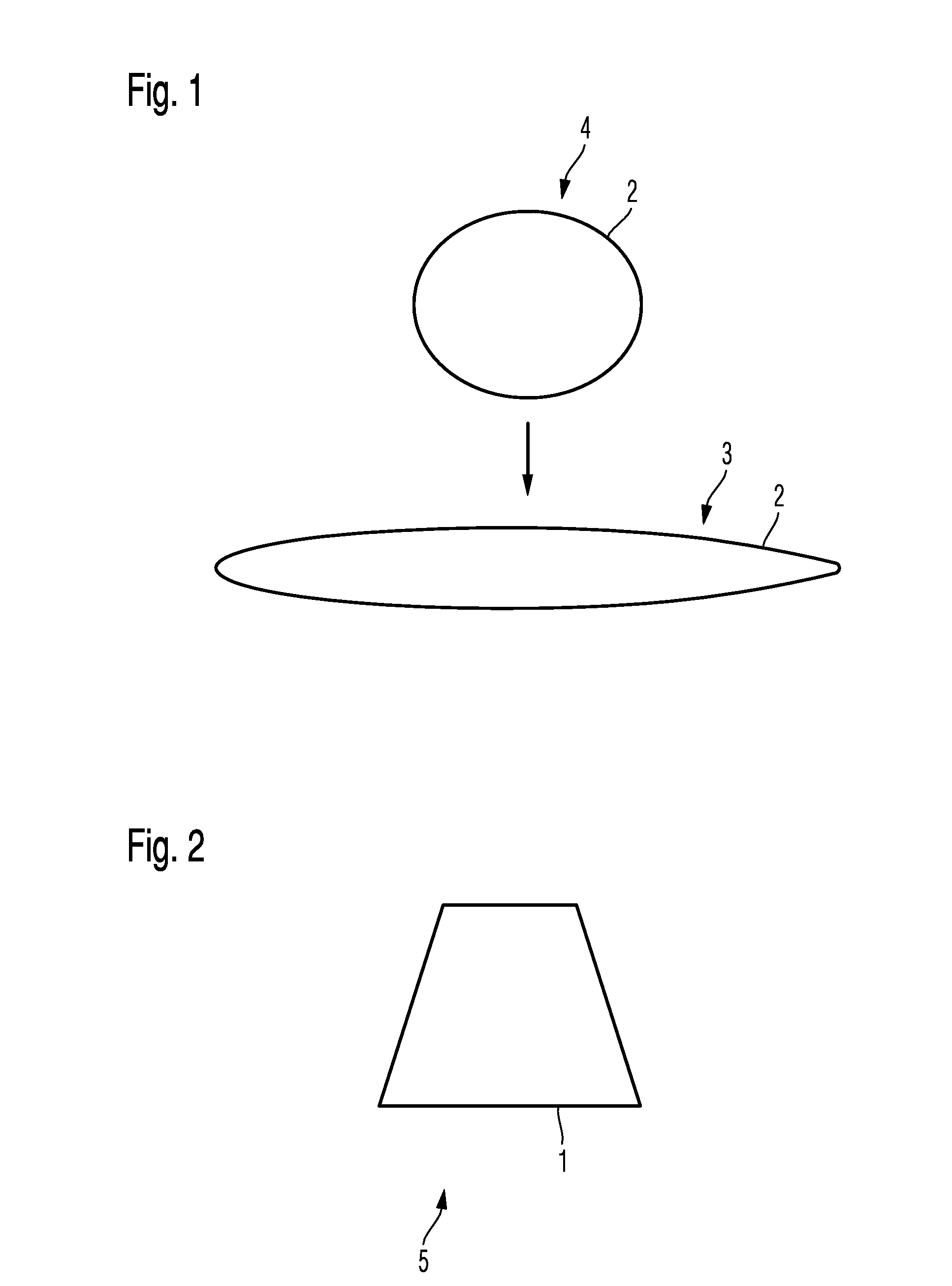
[0041]In the figures of the drawing the same reference symbols denote the same components or components with similar functions unless otherwise indicated.

[0042]FIG. 1 shows a cross-section of a conventional thin walled tube as semi-finished tube 2 with a round cross-section 4, respectively with a circular cross-section after the production by means of the blow extrusion method which might be folded plane 3 for transportation. This tube serves as semi-finished tube 2 for the production of a plastic foil tube 1 with an intended cross-section 6 which has a trapezoidal shape in the example shown in FIG. 2. This intended cross-section 6 is denoted in the following as second intended cross-section 6.

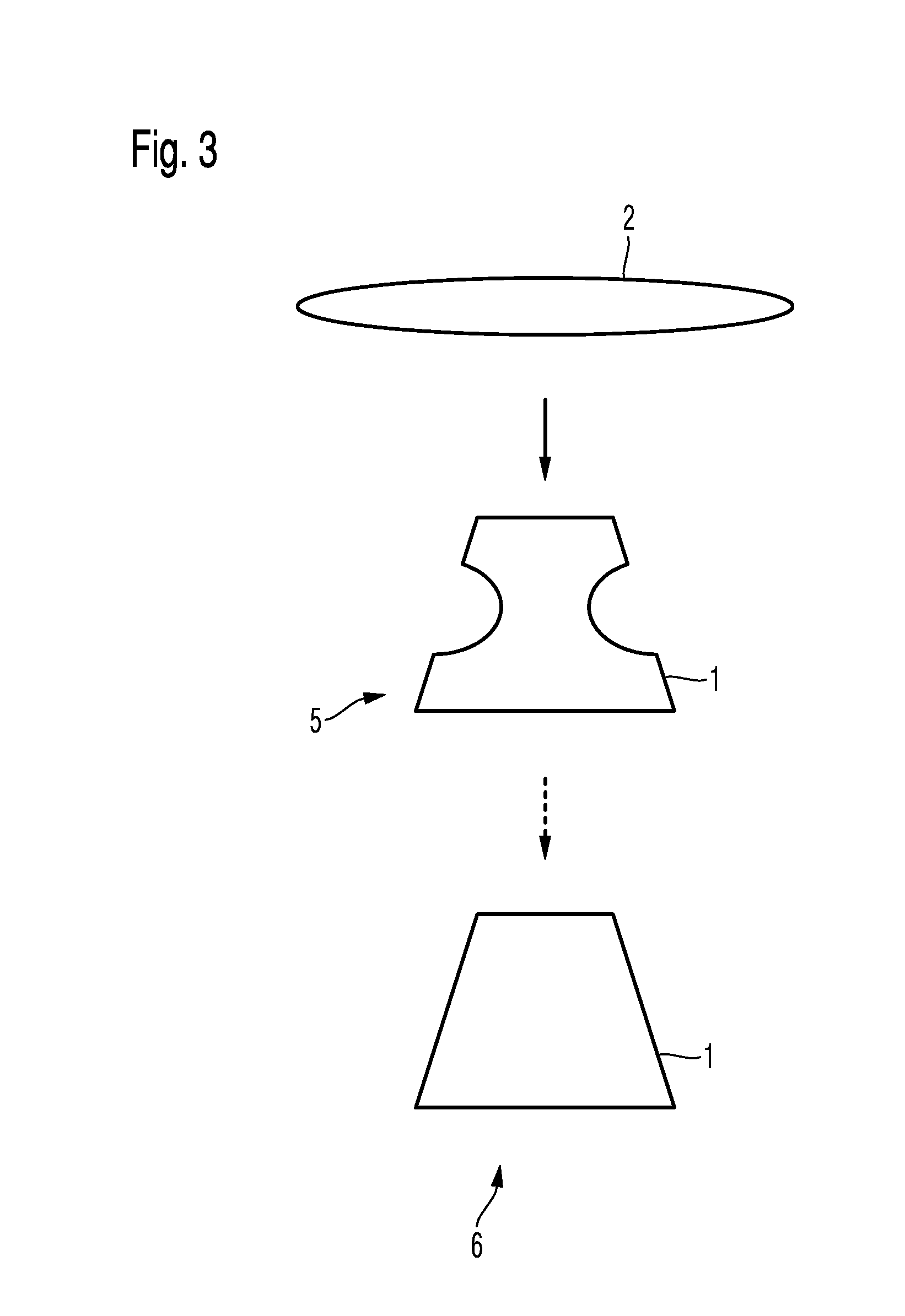
[0043]FIG. 3 schematically shows forming steps of the semi-finished tube 1 of FIG. 1 into a first intended cross-section 5 and into the second intended cross-section 6 according to an embodiment of an inventive method.

[0044]By means of the method according to the invention, tubes that are deno...


PUM

PropertyMeasurementUnit
Temperatureaaaaaaaaaa
Forceaaaaaaaaaa
Pressureaaaaaaaaaa

Abstract

The invention relates to a method for producing a plastic foil tube with an intended cross-section that derives from a circular cross-section as a means for the production of fiber compound components for aviation or aerospace. It comprises the following method steps: mounting a semi-finished tube on a core tool; charging the mounted semi-finished tube with a predetermined force to press the semi-finished tube on a core cross section of the core tool, wherein while charging the mounted semi-finished tube with the force crinkles are formed in longitudinal direction of the semi-finished tube; heating the semi-finished tube to a predetermined forming temperature for a predetermined time period for the production of the plastic foil tube with the intended cross-section and stripping the plastic foil tube which is formed in such a manner and cooled down off the core tool.

Description

CROSS-REFERENCE TO RELATED APPLICATIONS[0001]This application claims the benefit of U.S. Provisional Application No. 61 / 121,626, filed Dec. 11, 2008, the entire disclosure of which is herein incorporated by reference.FIELD OF THE INVENTION[0002]The present invention relates to a method for producing a plastic foil tube and to a plastic foil tube which is producible by means of such a method.[0003]According to the current state of the art the production of tubes with a cross-section that derives from a round cross-section, e.g. rectangular, squared and the like is not producible or only producible with strong restrictions concerning the formation of the geometry of the cross-section, the tolerance of the wall thickness and the development of the surface, respectively, by means of the so far used production methods. But, these kinds of tubes are needed for example for the production of hollow fiber composite components for thereby reaching a better structuring of the inner surface.[00...

Claims


Application Information

Patent Timeline
IPC IPC(8): B32B1/08B29C51/14
CPCB29C49/00B29C49/04B29C51/04B29C51/10B29C53/086Y10T428/1355B29C2049/0089B29C2791/006B29K2105/258B29L2023/003B29L2031/003B29C67/0025B29C2949/08
Inventor DORAWA, TOBIASJACOB, TORBEN
Owner AIRBUS OPERATIONS GMBH
Why Eureka
Try Eureka