Stator vane for a gas turbine engine

a technology of gas turbine engine and stator valve, which is applied in the direction of machines/engines, liquid fuel engines, lighting and heating apparatus, etc., can solve the problems of high stress on the stator valve and platform, and achieve the effect of reducing the stress concentration

Inactive Publication Date: 2010-06-17
GENERAL ELECTRIC TECH GMBH
View PDF7 Cites 17 Cited by
  • Summary
  • Abstract
  • Description
  • Claims
  • Application Information

AI Technical Summary

Benefits of technology

[0004]The invention addresses these problems. The present invention aims to provide a stator vane for a gas turbine with a platform having an improved design, which reduces the stress concentrations in the trailing edge of the stator vane and in the vane platform in the region of the trailing edge of the stator vane.
[0007]The recess in the vane platform in the area of the trailing edge of the stator vane reduces the stress concentrations in the trailing edge of the stator vane and in the vane platform in the area of the trailing edge of the stator vane. The low cycle fatigue and the creep rate in these areas are therefore reduced.

Problems solved by technology

As these stator vanes are subjected to the effects of the hot gases flowing out of the combustion chamber and of the high pressures, high stresses can arise in the stator vanes and the platforms.
This can lead to considerable stress concentrations, particularly in the trailing edge of the stator vane and in the platform in the area of the trailing edge of the stator vane.

Method used


Image

  • Stator vane for a gas turbine engine
  • Stator vane for a gas turbine engine
  • Stator vane for a gas turbine engine

Examples


Embodiment Construction

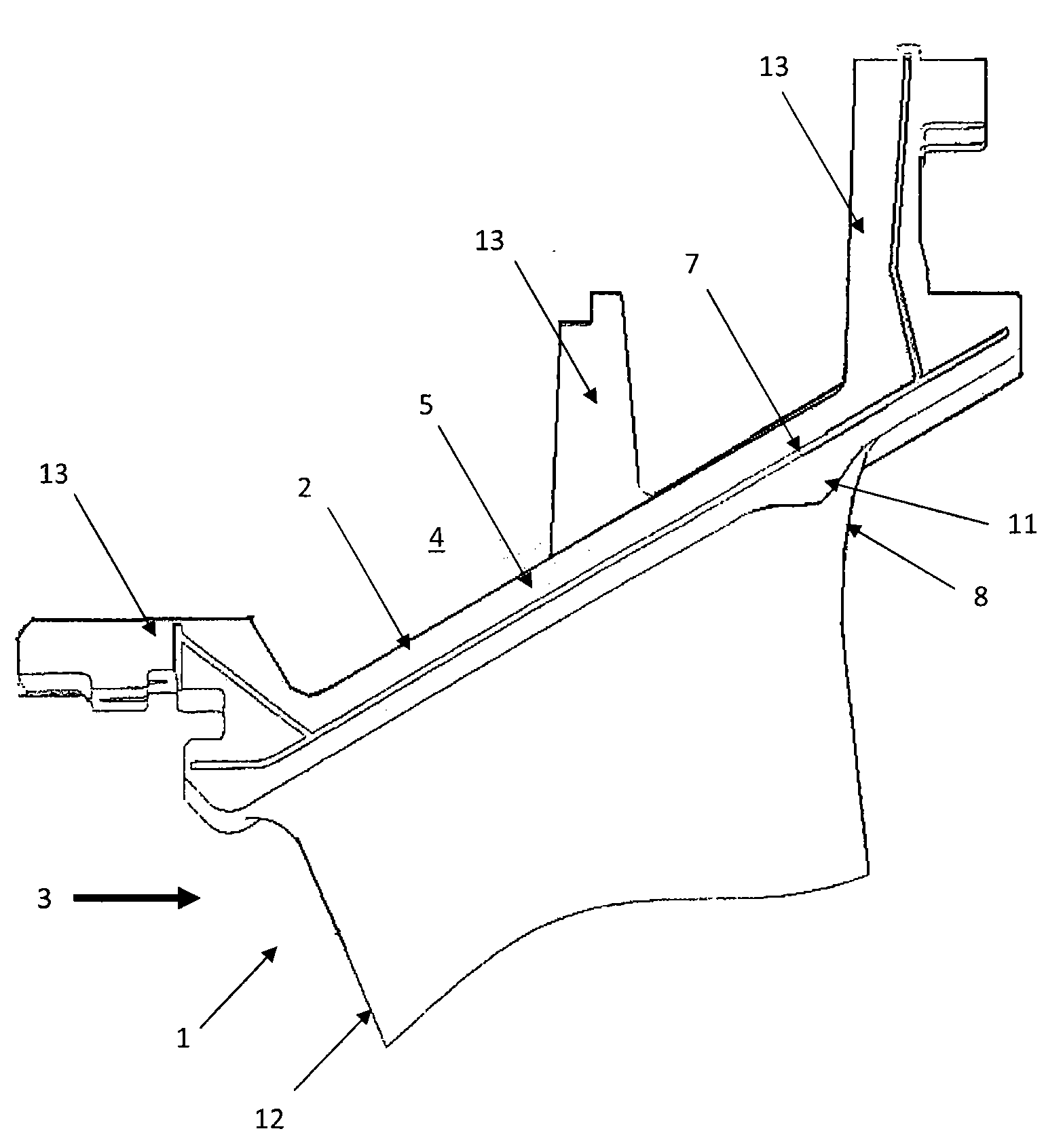
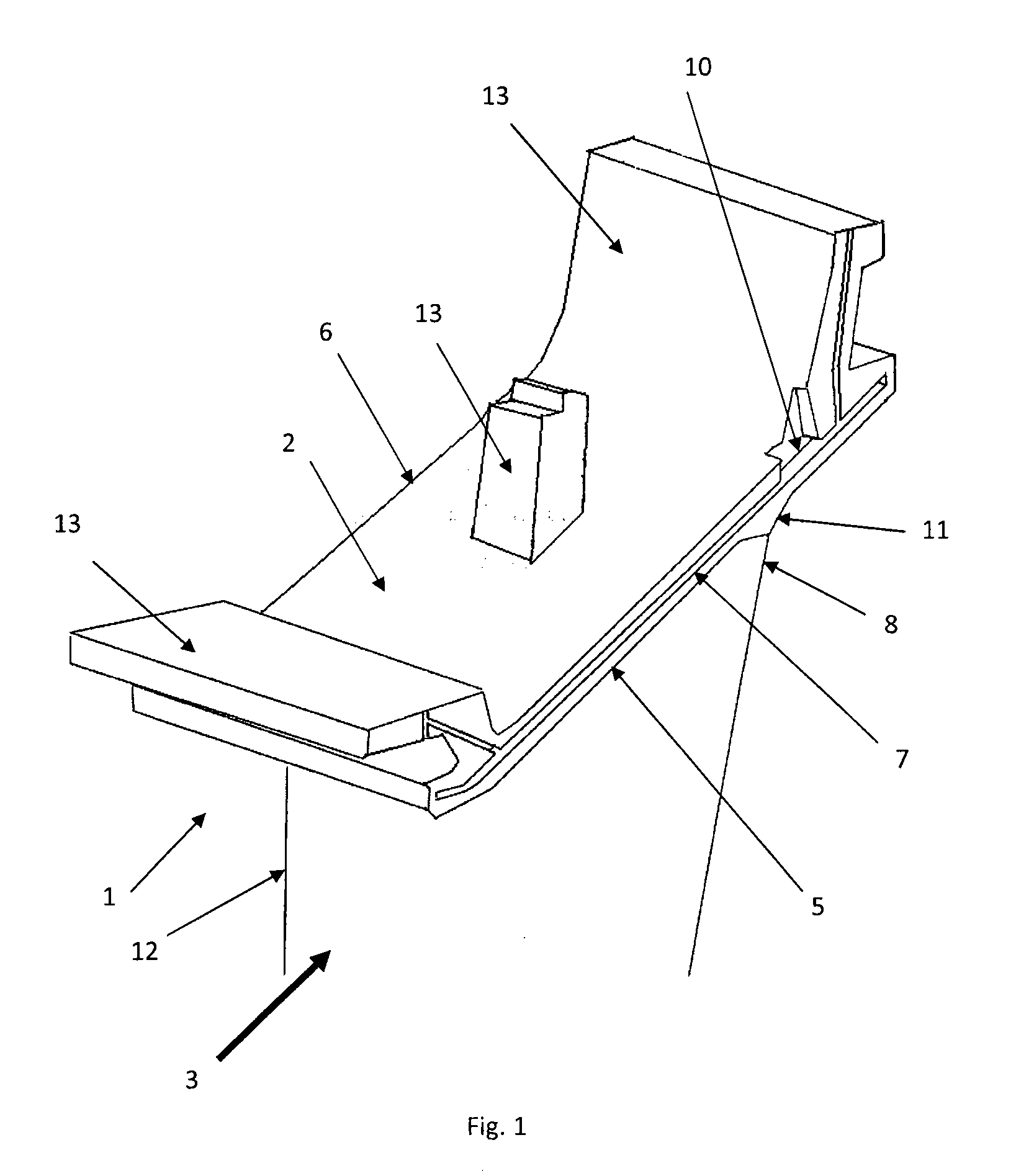
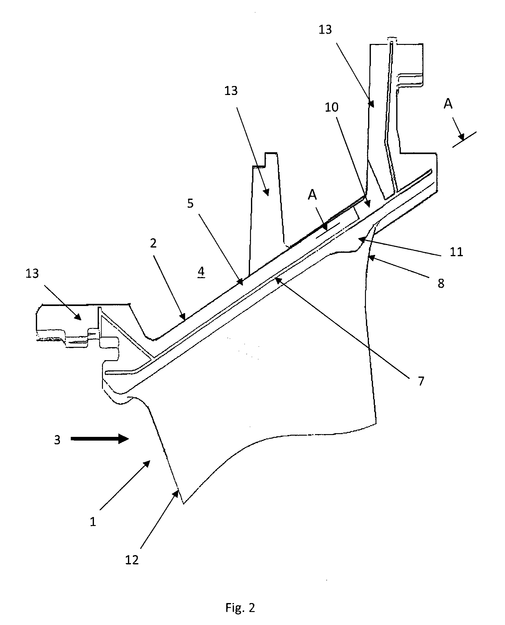
[0018]FIGS. 5 and 6 show a prior art stator vane 1 with a vane platform 2. In a gas turbine a plurality of such stationary stator vanes 1 are used, which are arranged in rows around the circumference of a turbine portion.

[0019]The stator vane 1 has a leading edge 12 and a trailing edge 8, whereby the vane platform 2 extends at least between the leading edge 12 and the trailing edge 8. Attachment elements 13 are provided on the radially outer side of the vane platform 2 for positioning the stator vane 1 in the radial and circumferential directions.

[0020]The vane platform 2 furthermore has side walls 5, 6 extending substantially in the longitudinal and radial directions of the turbine.

[0021]The vane platform 2 is located in the radial direction between a hot gas flow 3 and a space 4 filled with cooling air. In order to seal this space 4 from the hot gas flow the side walls 5, 6 are each provided with a groove 7 extending in the longitudinal direction of the vane platform 2. The groove...


PUM


Abstract

A guide vane for a gas turbine includes a vane body having a leading edge and a trailing edge and a shroud extending at least between the leading edge and the trailing edge. The shroud has a first side wall and a second side wall extending essentially radially and in a longitudinal direction of the gas turbine. The first side wall has a groove disposed in a region of the trailing edge extending in a longitudinal direction of the shroud and is configured to receive a sealing plate. The first side wall also has a clearance extending from the groove in a region of the trailing edge, wherein a depth of the clearance in a circumferential direction of the gas turbine is equal to a depth of the groove, and wherein a width of the clearance in the longitudinal direction of the shroud is between one to three times the depth of the clearance.

Description

[0001]This application is a continuation of International Patent Application No. PCT / EP2008 / 057947, filed on Jun. 23, 2008, which claims priority to Swiss Patent Application No. CH 01044 / 07, filed on Jun. 28, 2007. The entire disclosure of both applications is incorporated by reference herein.[0002]The present invention relates to a stator vane for a gas turbine engine, in particular a stator vane with a vane platform.BACKGROUND[0003]In a gas turbine a plurality of stationary stator or guide vanes are used which are arranged in rows along the circumference of the turbine portion. As these stator vanes are subjected to the effects of the hot gases flowing out of the combustion chamber and of the high pressures, high stresses can arise in the stator vanes and the platforms. The platform is situated between the hot gas flow and space filled with cooling air. In order to seal this space from the hot gases the platform usually has side walls which are provided with a groove extending in ...

Claims


Application Information

Patent Timeline
IPC IPC(8): F01D9/02
CPCF01D9/041F01D11/005F05D2240/11F05D2250/29F05D2240/80F05D2230/10F05D2240/57
Inventor KHANIN, ALEXANDERKURGANOV, IGORVORONTSOV, SERGEYODINOKOV, VICTOR
Owner GENERAL ELECTRIC TECH GMBH
Why Eureka
Try Eureka