
Charged particle used for electrophoretic display medium, electrophoretic display medium comprising the charged particle, and image display device using the electrophoretic display medium

a technology of electrophoretic display medium and charged particle, which is applied in the direction of instruments, cellulosic plastic layered products, natural mineral layered products, etc., can solve the problems of lowering the contrast of the displayed image and difficulty in achieving excellent image display, so as to increase the surface area to be charged, clear polarity, and the effect of sufficient charge potential

Inactive Publication Date: 2010-06-17
BROTHER KOGYO KK
View PDF6 Cites 4 Cited by
  • Summary
  • Abstract
  • Description
  • Claims
  • Application Information

AI Technical Summary

Benefits of technology

[0044]As described above, in the present invention, since it is possible to increase the surface area to be charged by attaching a charged first minute particle to a mother material, the charged particle can have a clear polarity and a sufficient charge potential, so that it is possible to provide excellent image displaying. Furthermore, when the charged particle comes into contact with a substrate or the like, a second attached material having a smaller adhesion force than that of the first minute particle mainly contacts with the substrate or the like, and thereby effectively preventing the charged particle from adhering to the substrate or the like, so that it is possible to display an excellent image with a high contrast. Therefore, according to the present invention, it is possible to obtain a charged particle to be used for an electrophoretic display medium capable of displaying an excellent image with a high contrast.
[0045]Moreover, in a display medium comprising the charged particle, and an image display device using the display medium, it is possible to achieve excellent image displaying with a high contrast as well.DESCRIPTION OF ILLUSTRATED EMBODIMENTS
[0046]A charged particle according to the present invention, a display medium comprising the charged particle, and an image display device using the display medium will be described in detail below referring to the drawings.(Description of One Embodiment of an Image Display Device According to the Present Invention)
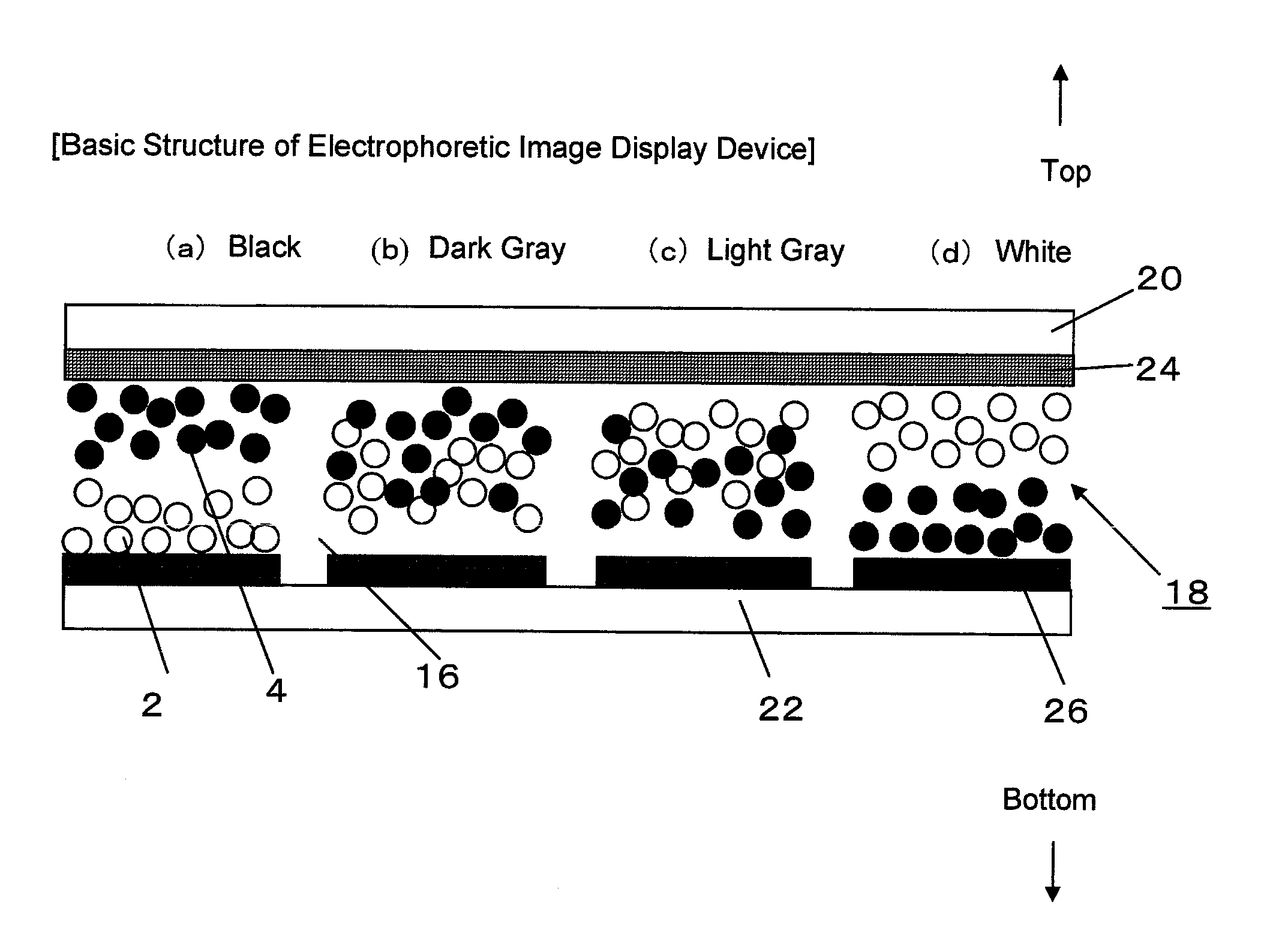
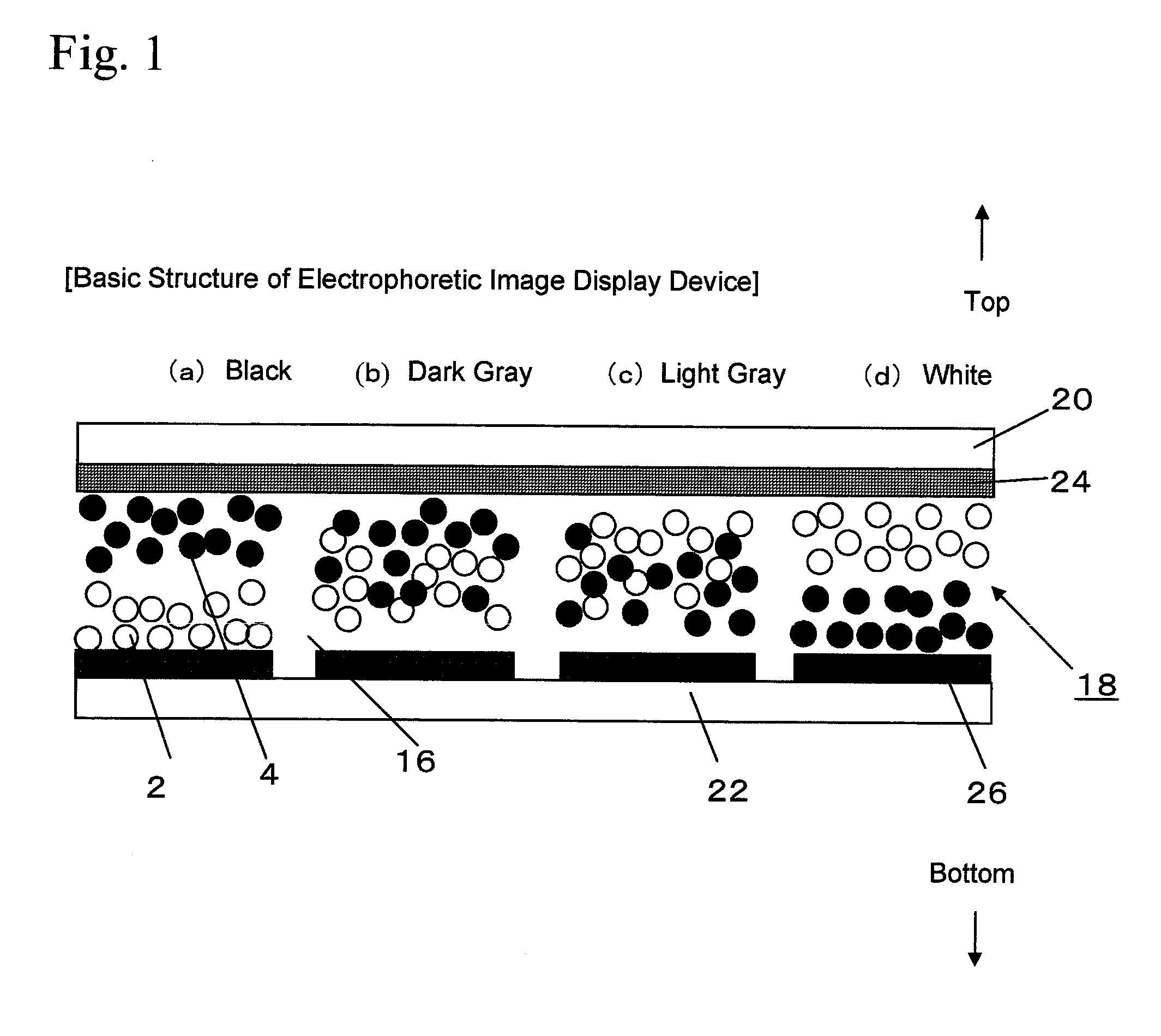
[0047]First, an embodiment of an image display device using a display medium comprising a charged particle according to the present invention will be described referring to FIG. 1. FIG. 1 is a sectional side view schematically showing an overall structure of an image display device 2, in which the upper side of the sheet corresponds to the display portion side of the image display device 2.
[0048]An image display device 18 comprises a transparent display substrate 20 disposed on the display portion side, a rear surface substrate 22 arranged approximately in parallel with the display substrate 20 with a predetermined distance therebetween. Furthermore, on the inner side (lower side of the sheet) of the display substrate 20, a common electrode 24 made of a transparent member is fixed, and on the inner side (upper side of the sheet) of the rear surface substrate 22, a plurality of pixel electrodes 26 each provided for each pixel are fixed.
[0049]In a sealed space formed between the display substrate 20 to which the common electrode 24 is fixed and the rear surface substrate 22 to which a plurality of pixel electrodes 26 are fixed, a display medium 16 comprising positively charged particles 2 and negatively charged particles 4 is enclosed. It should be noted that while black-colored particles are positively charged and white-colored particles are negatively charged as an example in this embodiment, it is not limited thereto.

Problems solved by technology

Accordingly, when a display medium comprising a negatively charged particle and a positively charged particle to which an oxide inorganic minute particle is attached is used, there arises a problem that it is difficult to achieve excellent image displaying, compared with a display medium comprising an appropriately positively charged particle and a negatively charged particle.
Furthermore, while it is possible to consider attaching as a minute particle that tend to be positively charged, for example, a resin minute particle, to deal with the aforementioned problem, such a resin minute particle have a large adhesion force, and thus when the charged particle comes into contact with a substrate or the like, due to the adhesion force of the attached resin minute particle, there arises a problem that the charged particle adheres to the substrate or the like, which results in lowering the contrast of the displayed image.

Method used


Image

  • Charged particle used for electrophoretic display medium, electrophoretic display medium comprising the charged particle, and image display device using the electrophoretic display medium
  • Charged particle used for electrophoretic display medium, electrophoretic display medium comprising the charged particle, and image display device using the electrophoretic display medium
  • Charged particle used for electrophoretic display medium, electrophoretic display medium comprising the charged particle, and image display device using the electrophoretic display medium

Examples


example 1

Description of Example Concerning Adhesion Force and Charged Polarity

[0074]First, samples of four types of charged particles: (1) Charged Particle 1, composed only of a mother particle; (2) Charged Particle 2, in which only a positively charged resin minute particle (first minute particle) is attached to a mother particle; (3) Charged Particle 3, in which only an oxide inorganic minute particle (second minute particle) is attached to a mother particle; and (4) Charged Particles 4, in which a resin minute particle (first minute particle) and an oxide inorganic minute particle (second minute particle) are attached to a mother particle, were prepared, and the adhesion forces and charged polarities of the prepared Charged Particles 1-4 were measured.

[0075]The detailed compositions of Charged Particles 1-4 are as follows: (1) Charged Particle 1, composed only of a mother particle made of carbon black-containing methacryl resin (PMMA); (2) Charged Particle 2, in which only an acryl resin ...

example 2

Description of Example Concerning Contrast

[0085]Next, a display medium was prepared by dispersing Charged Particles 1-4 (black-colored particles) prepared in the manner as described above and negatively charged particles (white-colored particles) in which silicon oxide (silica) is attached to a titanium oxide-containing methacryl resin (PMMA) particle, in a hydrocarbon-base solvent to which a small amount of alcohol is added. This display medium was enclosed between glass substrates with ITO disposed at a distance 25 μm apart from each other, and the brightness of the display surface was measured by a brightness measuring equipment (manufactured by TOPCON TECHNOHOUSE CORPORATION) to obtain contrast. Here, the contrast can be obtained from the ratio of the brightness at displaying white with respect to the brightness at displaying black, that is, the brightness of white display / the brightness of black display. The results of measurement are shown in Table 2.

TABLE 2SampleContrastCharg...

example 3

Description of Example Concerning Particle Size of Attached Minute Particles

[0087]Next, charged particles were prepared with differing in particle size ratio of a positively charged resin minute particle (first minute particle) relative to an oxide inorganic minute particle (second minute particle) attached to a positively charged mother particle, and the adhesion forces and contrasts were measured to examine the influence of particle size of minute particles attached.

[0088]Specifically, charged particles were prepared by using a positively charged methacryl resin (PMMA) particle as mother particle, adding thereto a positively charged acryl resin minute particle as positively charged resin minute particle, and further adding thereto a negatively charged silicon oxide (silica) minute particle as oxide inorganic minute particle. In this case, particle size ratio of an acryl resin minute particle relative to a silicon oxide (silica) minute particle varies from 0.4, 1.0, 1.3, to 2.0, an...


PUM

PropertyMeasurementUnit
Fractionaaaaaaaaaa
Electric potential / voltageaaaaaaaaaa
Fractionaaaaaaaaaa

Abstract

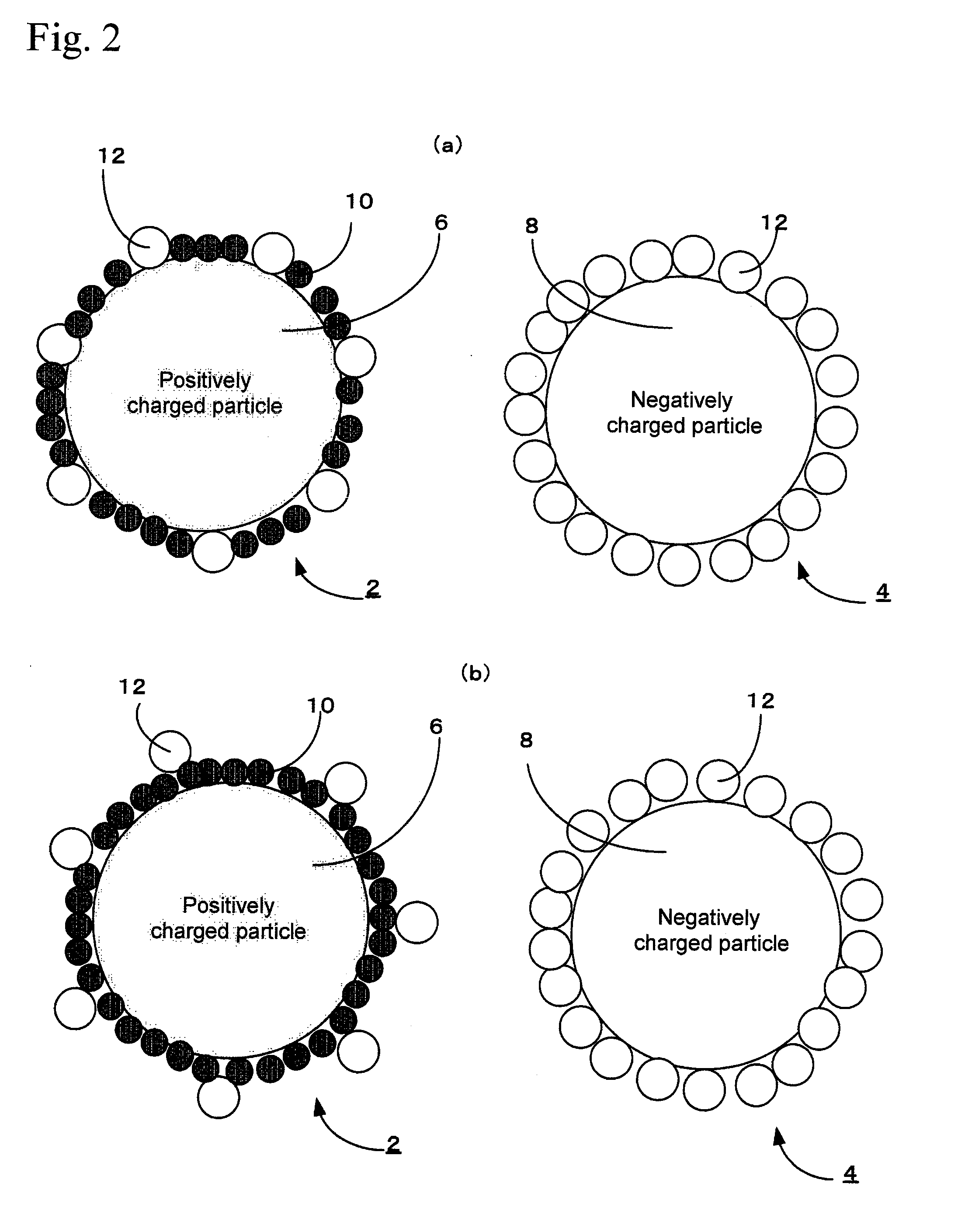
A charged particle to be used for an electrophoretic display medium in which a first attached material being charged with a predetermined polarity and a second attached material having a smaller adhesion force than that of the first attached material are attached to a mother particle, wherein the first attached material is a minute particle (hereinafter referred to as “first minute particle”), and the outermost surface of the second attached material is located outward relative to the outermost surface of the first minute particle in the radial direction of the mother particle, is provided.

Description

TECHNICAL FIELD[0001]The present invention relates to a positively or negatively charged particle used for an electrophoretic display medium, an electrophoretic display medium comprising the charged particle, and an image display device using the electrophoretic display medium.BACKGROUND ART[0002]Electrophoretic image display devices have recently been used in various fields including use as electronic paper. As an example of such electrophoretic image display devices, there can be exemplified an image display device in which a display medium comprising black-colored and white-colored charged particles is enclosed in a sealed space formed between a substrate on the display side where a common electrode is disposed and a substrate on the rear side where pixel electrodes are disposed. In this image display device, a black-colored charged particle and a white-colored charged particle are charged opposite, negative or positive, to each other, so that by changing the potential difference...

Claims


Application Information

Patent Timeline
IPC IPC(8): G02F1/167B32B5/16
CPCG02F1/167Y10T428/2991G02F2001/1678
Inventor OSHIKA, YUMIKO
Owner BROTHER KOGYO KK
Learn More