
Computer keyboard

a keyboard and computer technology, applied in the field of computer keyboards, can solve the problems of limited keyboard functions, and achieve the effect of increasing keyboard functions

Active Publication Date: 2010-06-17
LITE ON TECH CORP +1
View PDF9 Cites 76 Cited by
  • Summary
  • Abstract
  • Description
  • Claims
  • Application Information

AI Technical Summary

Benefits of technology

[0007]It is therefore one of the objectives of the present invention to provide a computer keyboard having a touch control display panel to display various editable electronic information, so as to realize independent adding or changing of keyboard control keys and increase functions for the keyboard.
[0011]Compared with the prior art, the computer keyboard of the present invention has following advantages:
[0013]2. Capable of starting or terminating various executable programs via electronic information displayed on the touch control display panel: based on links between the control keys and the executable programs in the host, people can execute programs by pressing the electronic function keys on the touch control display panel of the keyboard instead of using mouse to click corresponding hot key icon on the main display panel of the computer in the conventional way, and it is fast and more convenient for the people.
[0015]4. Capable of adding or removing control keys: according to dual-monitor display technology, when a controlled target is beyond display field of a certain monitor, it can be displayed on another monitor automatically. Thus, people can move selected hot keys from the main display panel of the computer to the touch control display panel of the keyboard in a dragging way. Users can select control keys according to requirements by themselves, to realize independent adding or changing of keyboard control keys to replace the conventional un-changeable mechanical control keys and increase functions for the keyboard.

Problems solved by technology

However, the positions and functions of the character keys on the keyboard are fixed, and users can not set the positions and functions of the character keys on the keyboard according to their requirements, but only can input command via fixed character keys.
The functions of the keyboard are limited.

Method used


Image

  • Computer keyboard
  • Computer keyboard
  • Computer keyboard

Examples


Embodiment Construction

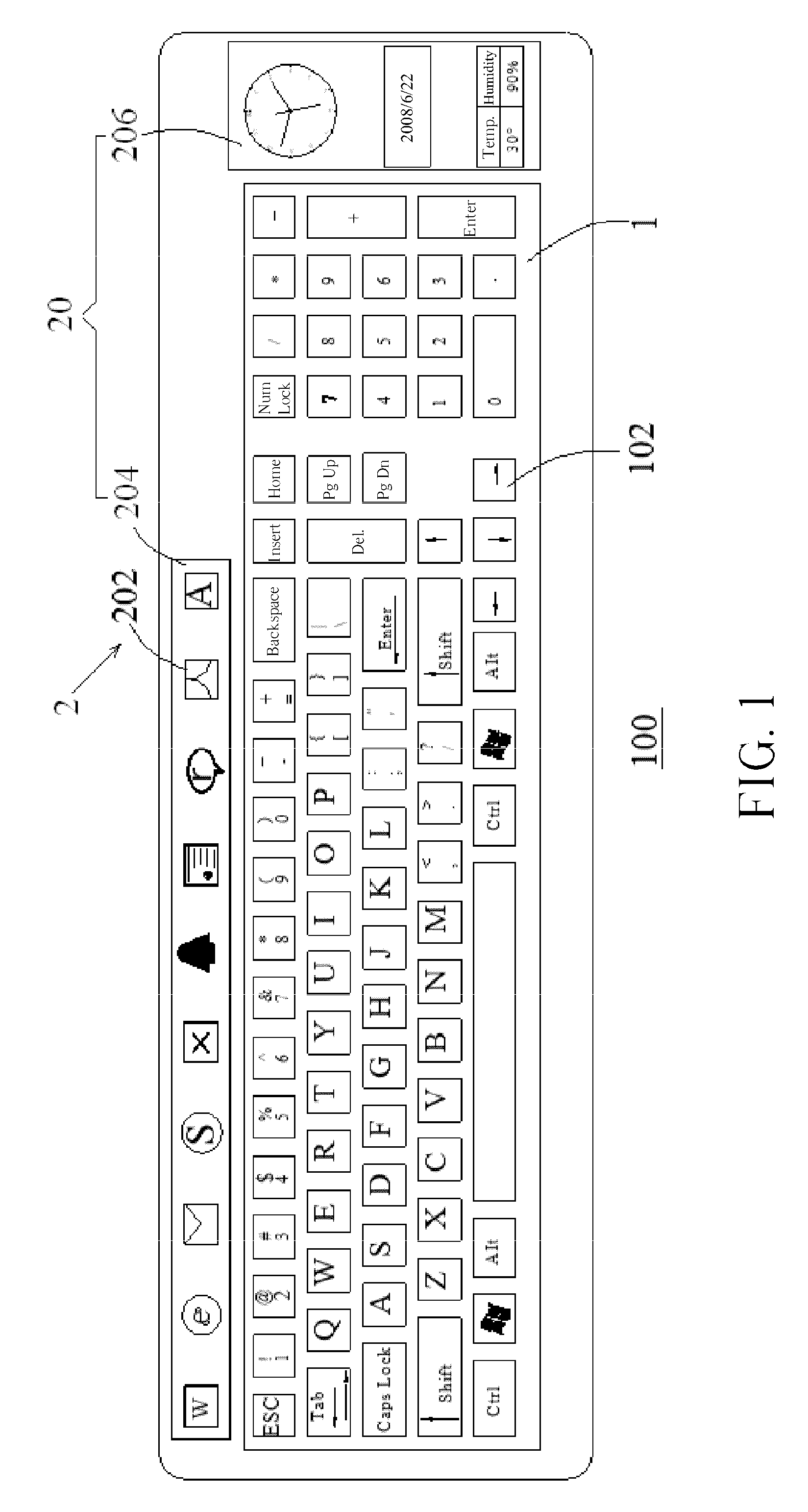
[0019]Please refer to FIG. 1 and FIG. 2. In an embodiment of the present invention, a computer keyboard 100 is provided. The computer keyboard 100 comprises a mechanical control key area 1 and a touch control display panel 2 coupled to a host 300, respectively. The mechanical control key area 1 has a plurality of mechanical control keys 102. The mechanical control keys 102 can be various mechanical function keys or character keys. Users can transmit control signals to the host 300 by pressing one or a plurality of mechanical control keys 102 to execute corresponding programs or operations.

[0020]The touch control display panel 2 is a touch control LCD panel, comprising a display unit 20, a plurality of touch sensing units 22, and a display control unit 24. The display unit 20 is utilized for displaying icons of a plurality of control keys 202, text, or patterns. The touch sensing units 22 are coupled to the host 300, and utilized for sensing pressed status of corresponding positions ...


PUM


Abstract

A computer keyboard comprises a touch control display panel comprising a display unit, a plurality of touch sensing units, and a display control unit. The display unit is utilized for displaying icons of control keys. The touch sensing units are utilized for sensing pressed status of the control keys, and transmitting pressure sensing signals and position signals to a host. The display control unit is utilized for receiving icons of the control keys from the host, and making the display unit display icons of the control keys. When an external force presses one of the control keys of the touch control display panel, a specific touch sensing unit senses pressed status of a position corresponding to the pressed control key, and make the host start or terminate an executable program according to link of the executable program corresponding to the pressed control key.

Description

BACKGROUND OF THE INVENTION[0001]1. Field of the Invention[0002]The present invention relates to a computer keyboard, and more particularly, to a computer keyboard having a touch control display panel.[0003]2. Description of the Prior Art[0004]In command to start executable programs in a computer more conveniently during using the computer, people often set hot keys linked to the executable programs as a way for starting the executable programs. In Microsoft Windows host, icons of the fast keys are placed in folders of the “desktop”. During the computer operation, the desktop displayed on the display panel is easy for people to click the hot keys to link the corresponding programs.[0005]As another important part of the computer, the keyboard is utilized for inputting various commands to the computer system. The conventional keyboard is made up by mechanical control key area, and there are fixed character keys in the mechanical control key area. In this way, users can press a specifi...

Claims


Application Information

Patent Timeline
IPC IPC(8): G06F3/02
CPCG06F3/0238G06F3/0213
Inventor GUO, YAN-LIANGCHEN, CHING-HUILEE, YUAN-YUAN
Owner LITE ON TECH CORP
Learn More