
Methods and system for model-based generic matching and tuning

a generic matching and model technology, applied in the field of method and system for model-based generic matching and tuning, can solve the problems of trial and error process, inability to simply utilize either scanner to image a given pattern, and high cost and time consumption

Active Publication Date: 2010-06-10
ASML NETHERLANDS BV
View PDF65 Cites 38 Cited by
  • Summary
  • Abstract
  • Description
  • Claims
  • Application Information

AI Technical Summary

Benefits of technology

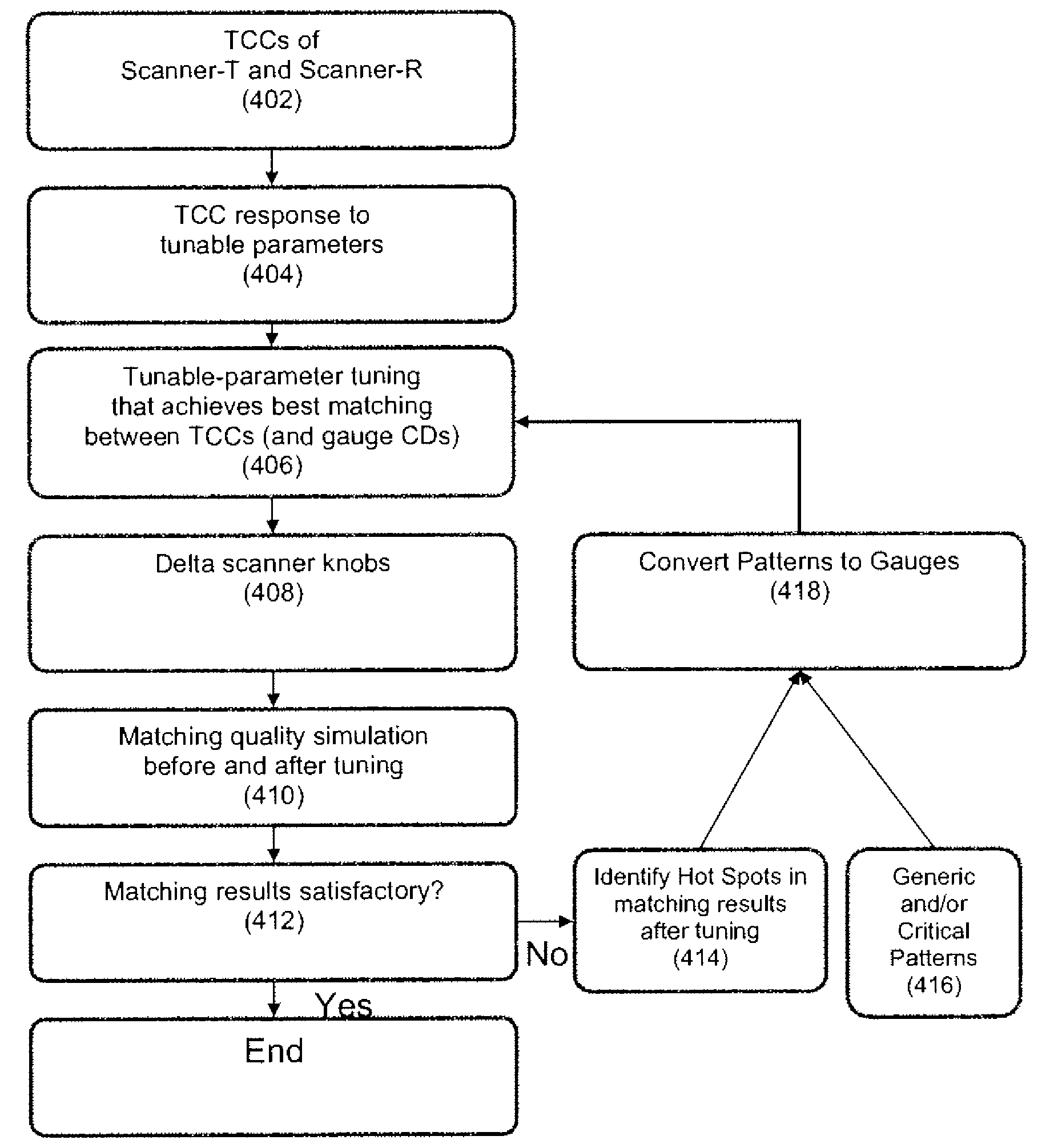
The present invention relates to a method for tuning lithography systems so that different lithography systems can image different patterns without requiring a trial and error process to optimize the process and system settings for each individual system. The method is based on a generic model-based matching and tuning approach that works for any pattern. The method can be combined with conventional techniques to deliver excellent performance for certain important patterns while achieving universal pattern coverage at the same time. The method involves obtaining lithographic process models for both the reference and to-be-tuned lithographic processes, identifying tunable parameters of the to-be-tuned process, determining responses of the process model to changes in the tunable parameters, determining optimal changes in the tunable parameters to match the process models, and adjusting the process model for the to-be-tuned process based on the determined optimal changes.

Problems solved by technology

These rules are set by processing and design limitations.
Indeed, this is often a trial and error process wherein the scanner settings are selected and the desired pattern is imaged and then measured to determine if the resulting image is within specified tolerances.
As such, it is not possible to simply utilize either scanner to image a given pattern, as the resulting image can vary considerably.
Currently, this is typically accomplished by a trial and error process, which as noted above, is both expensive and time consuming.
This may be very time consuming and expensive.
It is also pattern specific, that is, there is no guarantee of matching for patterns not selected.

Method used


Image

  • Methods and system for model-based generic matching and tuning
  • Methods and system for model-based generic matching and tuning
  • Methods and system for model-based generic matching and tuning

Examples


Embodiment Construction

[0019]The present invention will now be described in detail with reference to the drawings, which are provided as illustrative examples of the invention so as to enable those skilled in the art to practice the invention. Notably, the figures and examples below are not meant to limit the scope of the present invention to a single embodiment, but other embodiments are possible by way of interchange of some or all of the described or illustrated elements. Moreover, where certain elements of the present invention can be partially or fully implemented using known components, only those portions of such known components that are necessary for an understanding of the present invention will be described, and detailed descriptions of other portions of such known components will be omitted so as not to obscure the invention. Embodiments described as being implemented in software should not be limited thereto, but can include embodiments implemented in hardware, or combinations of software and...


PUM


Abstract

The present invention relates to a method for tuning lithography systems so as to allow different lithography systems to image different patterns utilizing a known process that does not require a trial and error process to be performed to optimize the process and lithography system settings for each individual lithography system. According to some aspects, the present invention relates to a method for a generic model-based matching and tuning which works for any pattern. Thus it eliminates the requirements for CD measurements or gauge selection. According to further aspects, the invention is also versatile in that it can be combined with certain conventional techniques to deliver excellent performance for certain important patterns while achieving universal pattern coverage at the same time.

Description

CROSS-REFERENCE TO RELATED APPLICATIONS[0001]The present application claims priority to U.S. Prov. Appln. No. 61 / 113,024 filed Nov. 10, 2008, the contents of which are incorporated by reference herein in their entirety.FIELD OF THE INVENTION[0002]The technical field of the present invention relates generally to a method and system for performing model-based scanner tuning and optimization so as to allow for optimization of performance of multiple lithography systems for generic patterns.BACKGROUND OF THE INVENTION[0003]Lithographic apparatuses can be used, for example, in the manufacture of integrated circuits (ICs). In such a case, the mask may contain a circuit pattern corresponding to an individual layer of the IC, and this pattern can be imaged onto a target portion (e.g. comprising one or more dies) on a substrate (silicon wafer) that has been coated with a layer of radiation-sensitive material (resist). In general, a single wafer will contain a whole network of adjacent target...

Claims


Application Information

Patent Timeline
Patent Type & Authority Applications(United States)
IPC IPC(8): G06F17/50
CPCG03F1/144G03F1/36G03F7/70483G06F17/5081G03F7/70525G03F7/70991G03F7/705G03F1/70G06F30/398G06F30/39
Inventor CAO, YUFENG, HANYINGYE, JUN
Owner ASML NETHERLANDS BV
Learn More