Low cost broadband wireless communication system

a wireless communication system and low-cost technology, applied in the field of wireless communications systems, can solve the problems of complex calculation methods used in the modem circuit, and achieve the effects of reducing size and cost, sacrificing functionality, performance or reliability, and high data ra

Inactive Publication Date: 2005-06-09
REVEAL IMAGING
View PDF28 Cites 130 Cited by
  • Summary
  • Abstract
  • Description
  • Claims
  • Application Information

AI Technical Summary

Benefits of technology

[0007] This present invention advantageously reduces the size and cost of prior art high data rate wireless communication systems using an outdoor unit by a factor of ten without sacrificing the functionality, performance or reliability, which are so important in broadband communications. The system architecture of the present invention includes an indoor unit (IDU), and a compact outdoor unit (ODU), which includes an intermediate frequency / modem circuit. A unique and unobvious digital interface is provided between the indoor unit and the outdoor unit, which is capable of at least about 100 MBps data rate over a minimum of about a 300 meter cable as one non-limiting example.
[0008] Prior art existing modem circuits have used complex calculation methods based upon the Cartesian coordinate system because the modems receive Cartesian data. The present invention, however, converts to a polar coordinate system at the receiver, at the earliest possible system state, and completes all further calculations in the polar coordinate system. This reduces the computational requirements, and therefore, reduces the size and cost of the overall system.
[0009] The present invention also provides a highly-integrated, low-cost, compact outdoor unit (ODU) with a built-in modem circuit. A flexible system architecture supports Quadrature Phase Shift Keying (QPSK) and Quadrature Amplitude Modulation (QAM) direct modulation / demodulation, resulting in high data rates exceeding 100 Megabits / Sec. The novel and unobvious modem design of the present invention reduces complexity and costs of the overall system by performing all computations in polar coordinates instead of Cartesian coordinates. A low-cost, high-data rate digital interface between the indoor unit and the outdoor unit eliminates the requirement for locating costly, radio frequency (RF) components in the indoor unit. The use of low-cost predistortion methods allows the measurement and correction of high-powered amplifier non-linearity.

Problems solved by technology

Prior art existing modem circuits have used complex calculation methods based upon the Cartesian coordinate system because the modems receive Cartesian data.

Method used


Image

  • Low cost broadband wireless communication system
  • Low cost broadband wireless communication system
  • Low cost broadband wireless communication system

Examples


Embodiment Construction

[0025] The present invention will now be described more fully hereinafter with reference to the accompanying drawings, in which preferred embodiments of the invention are shown. This invention may, however, be embodied in many different forms and should not be construed as limited to the embodiments set forth herein. Rather, these embodiments are provided so that this disclosure will be thorough and complete, and will fully convey the scope of the invention to those skilled in the art. Like numbers refer to like elements throughout.

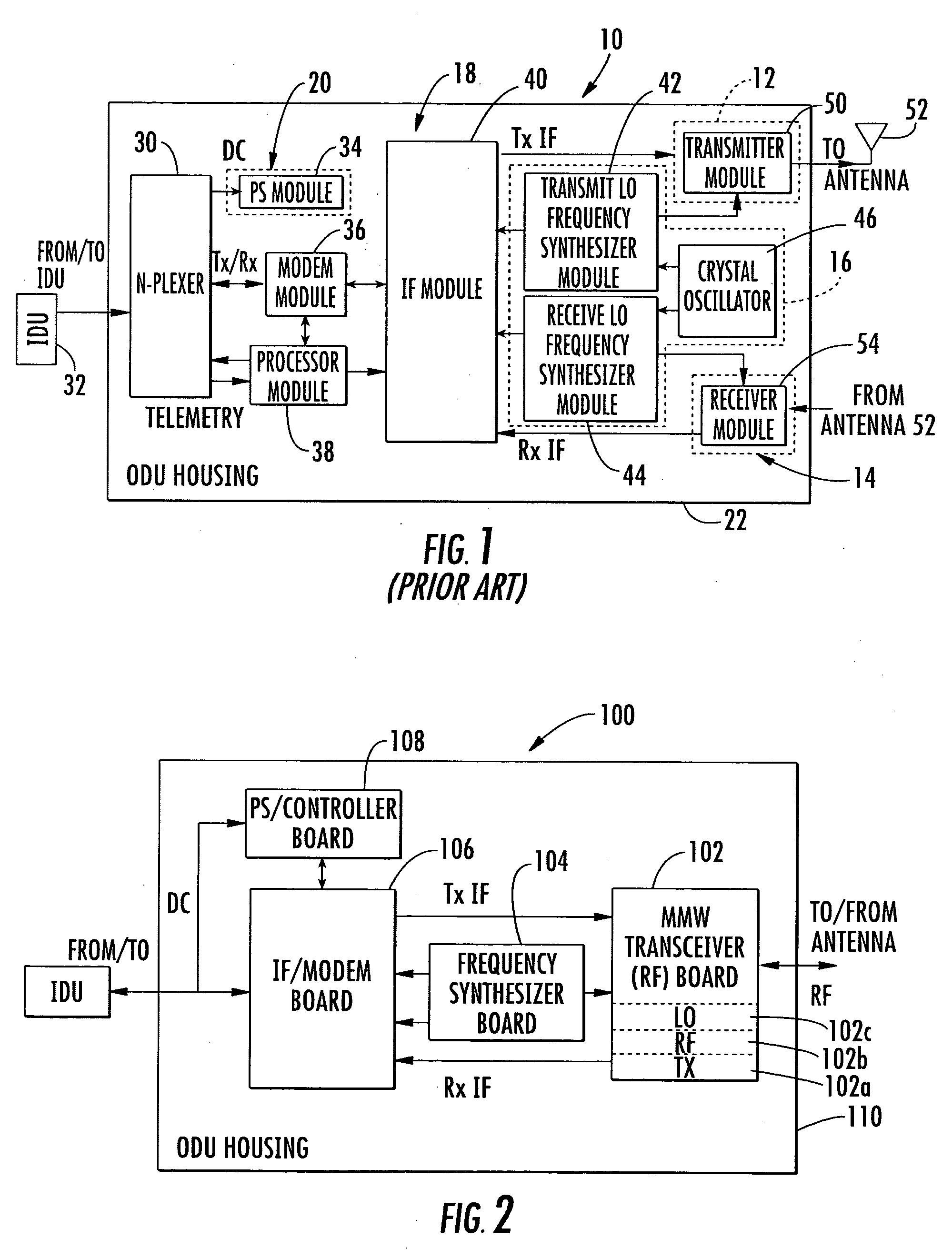
[0026]FIG. 1 is a block diagram of a prior art wireless, terrestrial outdoor unit 10 commonly used throughout the industry. This prior art outdoor unit 10 includes five subassemblies: 1) a millimeter wave (MMW) transmit section shown by dashed lines at 12; 2) a MMW receiver section shown by dashed lines at 14; 3) a frequency synthesizer section shown by the dashed lines at 16; 4) an IF / Processor section 18; and 5) a power supply (PS) section 20, typicall...


PUM


Abstract

This present invention includes an indoor unit (IDU) and compact outdoor unit (ODU) having an intermediate frequency / modem circuit, millimeter wave transceiver circuit, and digital interface between the IDU and the ODU capable of up to about 100 MBps data rate over at least about a 300 meter cable. The system uses a conversion to the polar coordinate system completes calculations in the polar coordinate system, reducing the computational requirements, and therefore, the size and cost of the system.

Description

RELATED APPLICATION [0001] This application is based upon prior filed copending provisional application Ser. No. 60 / 527,911 filed Dec. 8, 2003.FIELD OF THE INVENTION [0002] This invention relates to the field of wireless communications systems, and more particularly, this invention relates to millimeter wave wireless communications systems that include an indoor unit and an outdoor unit. BACKGROUND OF THE INVENTION [0003] Co-pending and commonly-assigned U.S. patent application Ser. No. 10 / 338,773 filed Jan. 8, 2003, the disclosure which is hereby incorporated by reference in its entirety, discloses a millimeter wave (MMW) outdoor unit that overcomes the disadvantages associated with the increased demand for high-speed, high-data rate communication requiring broadband access to any related network infrastructure. The outdoor unit overcomes the prior art problem of fabricating and testing outdoor units that are expensive, require manual labor, and have low operational reliability. It...

Claims


Application Information

Patent Timeline
IPC IPC(8): H04B1/38
CPCH04B1/38
Inventor AMMAR, DANNY F.BILLS, DAVID M.
Owner REVEAL IMAGING
Why Eureka
Try Eureka