Controlling dynamic and thermal loads on laser beam positioning system to achieve high-throughput laser processing of workpiece features

Active Publication Date: 2010-06-10
ELECTRO SCI IND INC
View PDF16 Cites 37 Cited by
  • Summary
  • Abstract
  • Description
  • Claims
  • Application Information

AI Technical Summary

Benefits of technology

[0011]A method of accomplishing high-throughput laser processing of densely spaced workpiece features minimizes workpiece feature processing inaccuracy and quality degradation that result from dynamic and thermal loads on laser beam positioning and optical components directing the laser beam during workpiece feature processing. A preferred embodiment entails positioning on a support a workpiece having a process surface that defines a process surface area and directing a laser beam to a beam positioning system to provide a processing laser beam for incidence at feature locations aligned along a processing band on the process surface. The beam positioning system includes a movable stage and first and second beam positioners that cooperate with the movable stage to process workpiece features at the feature locations on the process surface. The first beam positioner is characterized by a first response time and is operable to position the processing laser beam within a scan field region of the process surface. The second beam positioner includes a zero-inertia optical deflector of an acousto-optic type characterized by a second response time and operable to move the processing beam to locations within the scan field region. The second response time is shorter than the first response time and preferably shorter than the inter-pulse period of the processing laser.
[0012]The preferred method also entails controlling the beam positioning system to perform several functions. The first function is to coordinate operation of the movable stage and the first beam positioner to position the processing laser beam within the scan field region and move the scan field region to cover the process surface. The scan field region is substantially smaller than the process surface area of the workpiece and includes multiple processing bands that each encompass multiple feature locations. The second function is to operate the first beam positioner to successively position the processing laser beam to the multiple processing bands within the scan field region. The third function is to operate the second beam positioner to process the workpiece features at the multiple feature locations in each of the processing bands. This is accomplished by moving the processing laser beam to and dwelling the processing laser beam at each feature location to process the workpiece features in the processing band. A beneficial result is that the first beam positioner undergoes negligible acceleration and deceleration during workpiece feature processing within the scan field region. Another beneficial result is that the processing laser beam is moved to new feature locations within its inter-pulse period, thereby eliminating move time (during processing along the processing band) and increasing throughput.

Problems solved by technology

Each of these approaches has certain limitations.
If a very large scan lens is used to cover the entire workpiece field, the large lens is subject to accuracy degradation caused by optics heating that results from working with high-powered laser beams.
Such large beam diameters require large galvos, which in turn suffer from accuracy effects resulting from the lower thermal efficiency of moving large (high-inertia) mirrors with large (high-inertia) galvos.
The processing system suffers, however, from the effects of non-telecentric beam delivery, which degrades the quality of the drilled vias.
This leads to thermal accuracy issues similar to those described above because of the large galvos required in such systems.
The disadvantages of this approach are cost, complexity, inaccuracy contribution by the focus element; cost of the focus element for very high-speed applications; and residual telecentric error.
As the galvo rapidly scans over its field, the galvo must spend a significant amount of time accelerating and decelerating at the edges of the scan field because it is significantly smaller than the workpiece.
This expenditure of time causes a significant reduction in throughput, and if high acceleration is used to reduce the turnaround time, thermal heating of the galvo degrades accuracy and places an upper limit on achievable acceleration.
Yet this approach may be infeasible because of the throughput limitation described above, depending on the number of laser pulses required to process each via.

Method used


Image

  • Controlling dynamic and thermal loads on laser beam positioning system to achieve high-throughput laser processing of workpiece features
  • Controlling dynamic and thermal loads on laser beam positioning system to achieve high-throughput laser processing of workpiece features
  • Controlling dynamic and thermal loads on laser beam positioning system to achieve high-throughput laser processing of workpiece features

Examples


Embodiment Construction

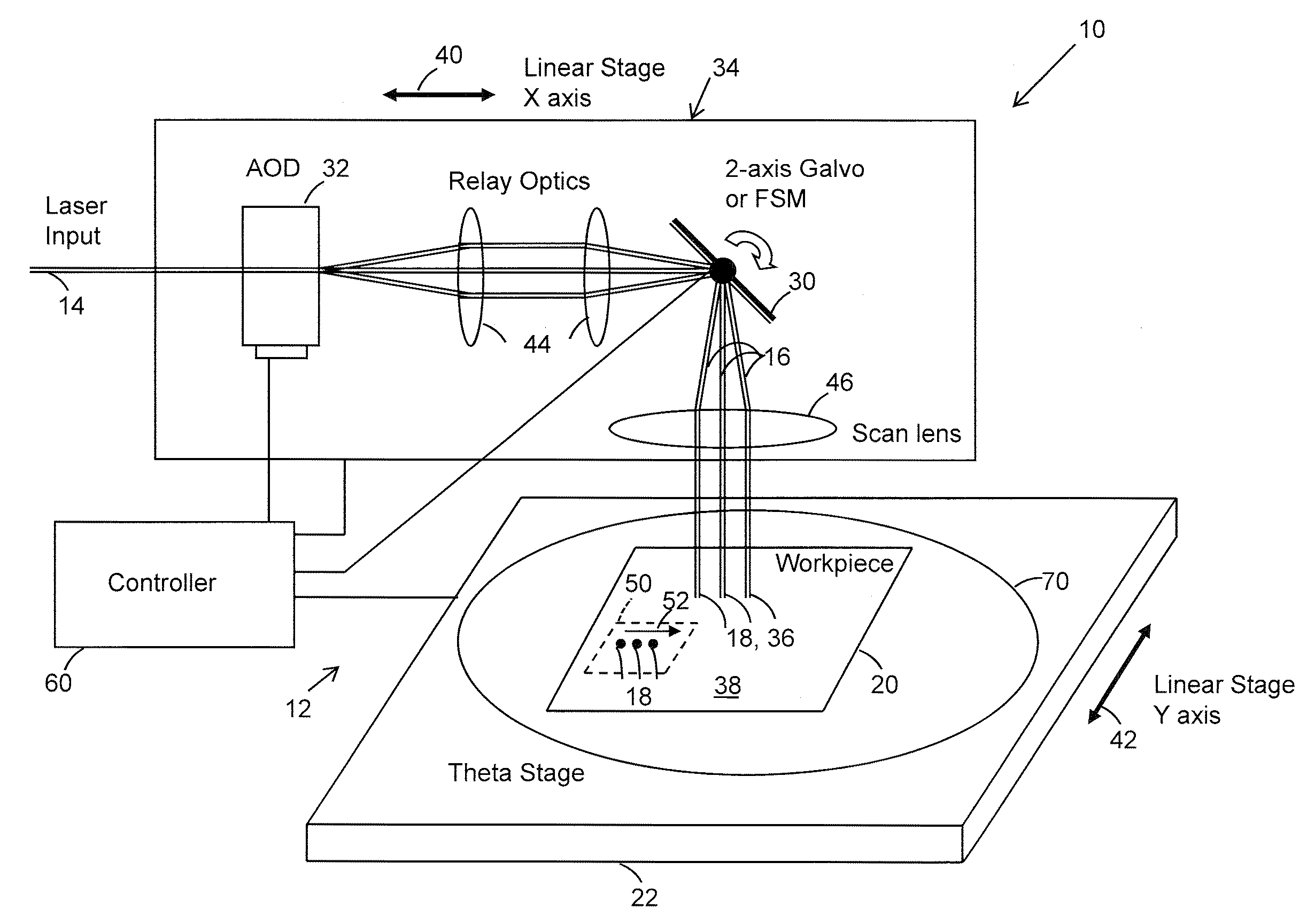
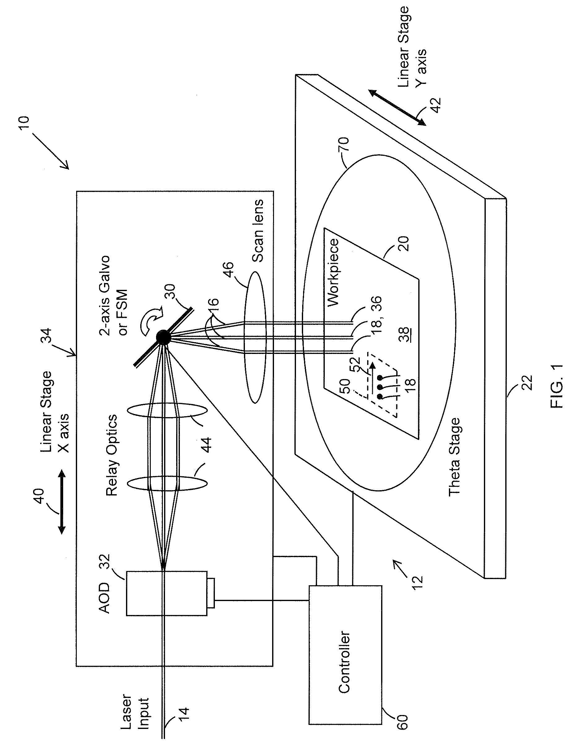
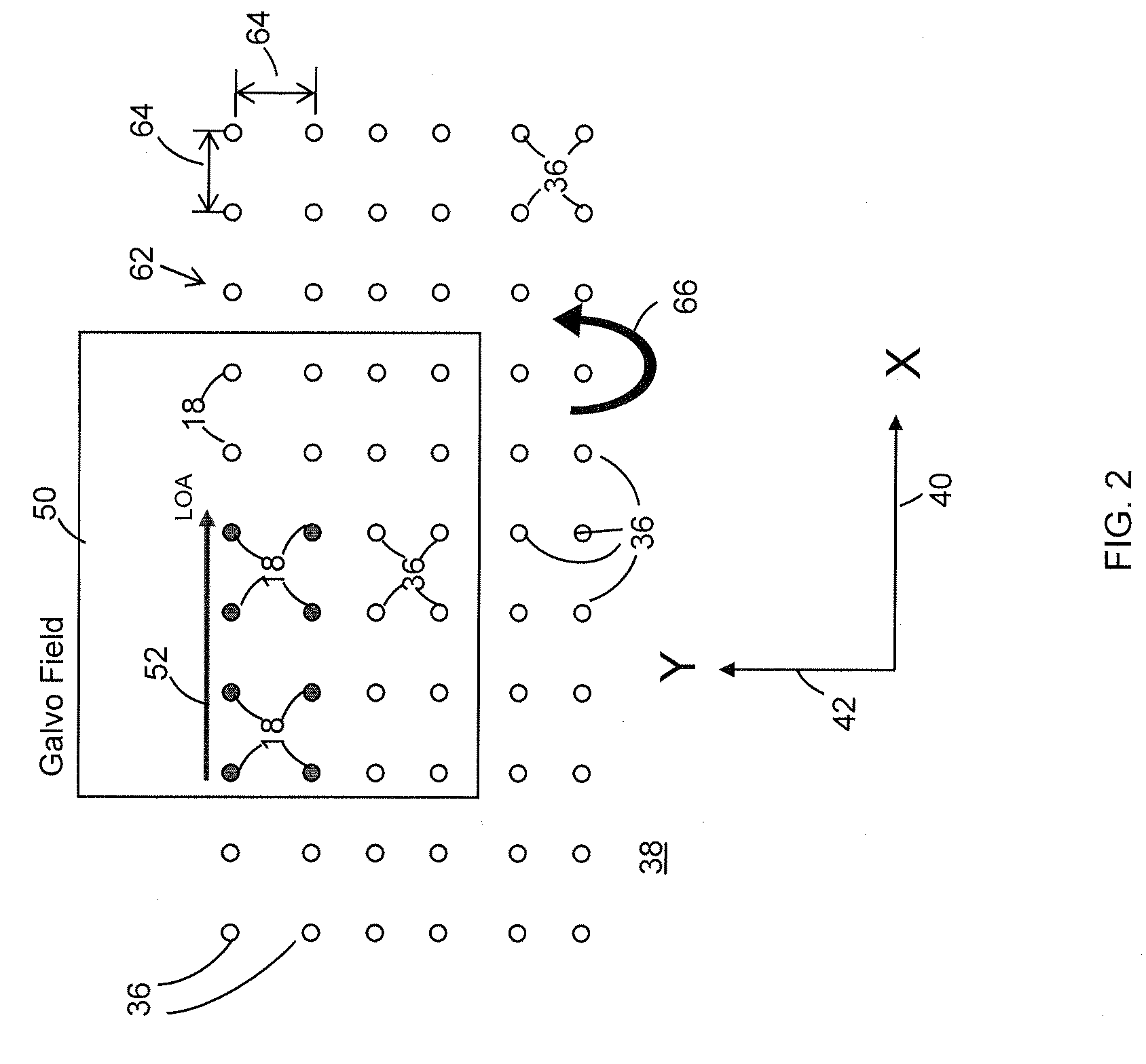
[0018]FIG. 1 shows the hardware architecture of a preferred embodiment of a laser beam positioning system 10 of a laser-based specimen processing system 12. Beam positioning system 10 receives an input laser beam 14 and directs it to form a processing laser beam 16 that processes target features 18 of a workpiece 20 mounted on a support 22. Beam positioning system 10 includes as a first beam positioner a mirror-based beam positioner 30 and as a second beam positioner a zero-inertia optical deflector 32 that cooperate with a movable stage 34 to direct processing beam 16 to process target features 18 at target feature locations 36 on a process surface 38 of workpiece 20. A preferred zero-inertia optical deflector 32 is an acousto-optic deflector (AOD) such as, for example, a Neos 45100-5-6.5 DEG-.51 one-dimensional deflector, which is available from Neos Technologies, Inc., Melbourne, Fla. Mirror-based beam positioner 30 may be a two-axis fast steering mirror (FSM) or a two-axis galva...


PUM

PropertyMeasurementUnit
Lengthaaaaaaaaaa
Surface areaaaaaaaaaaa

Abstract

A method of accomplishing high-throughput laser processing of workpiece features arranged in a densely spaced pattern minimizes workpiece feature processing inaccuracy and quality degradation that result from dynamic and thermal loads on laser beam positioning and optical components directing the laser beam during workpiece feature processing. A preferred embodiment is implemented with a laser beam positioning system composed of a zero-inertia optical deflector of an acousto-optic beam deflector (AOD) or an electro-optical deflector (EOD) type, a galvanometer head, and a linear stage cooperating to position the laser beam among the workpiece features.

Description

COPYRIGHT NOTICE[0001]©2008 Electro Scientific Industries, Inc. A portion of the disclosure of this patent document contains material that is subject to copyright protection. The copyright owner has no objection to the facsimile reproduction by anyone of the patent document or the patent disclosure, as it appears in the Patent and Trademark Office patent file or records, but otherwise reserves all copyright rights whatsoever. 37 CFR §1.71(d).TECHNICAL FIELD[0002]This disclosure relates to laser processing workpiece features and, in particular, to performing high throughput laser processing of densely spaced workpiece features while minimizing degradation of accuracy and workpiece feature quality that result from dynamic and thermal loads on laser beam positioning and optical system components.BACKGROUND INFORMATION[0003]Certain laser processing applications require extremely high throughput processing of a regularly spaced pattern of target locations on a workpiece. For instance, ce...

Claims


Application Information

Patent Timeline
IPC IPC(8): B23K26/00B23K26/02
CPCB23K26/0807B23K26/0823B23K2201/40B23K26/381B23K26/4075B23K26/0853B23K26/40B23K26/082B23K26/382B23K2101/40B23K2103/50Y02E10/50B23K26/042H01L31/042
Inventor UNRATH, MARK A.
Owner ELECTRO SCI IND INC
Why Eureka
Try Eureka