Method for detecting leakage from a pipe

a leakage detection and pipe technology, applied in seismology, gas/liquid distribution and storage, geological measurements, etc., can solve the problems of loss of data, loss of sensitivity or an unacceptable level of false alarms, and difficulty in monitoring and managing a large-scale system, so as to prolong the battery life, reduce the volume of transmitted data, and reduce power consumption

Inactive Publication Date: 2010-06-10
SAMUELSON JOSEF
View PDF3 Cites 4 Cited by
  • Summary
  • Abstract
  • Description
  • Claims
  • Application Information

AI Technical Summary

Benefits of technology

[0020]1. A modular, distributed system allows to protect a large area.
[0043]Thus, the sensor units do not need their batteries to be replaced too often, which may otherwise present an expensive maintenance demand.

Problems solved by technology

Acoustic and / or other types of sensors buried in the ground may be used for that purpose, however there are problems with implementing such a system—how to connect a multitude of sensors, how to process a multitude of signals from such sensors, etc.
The operation of a large scale system is difficult to monitor and manage.
There may be loss of sensitivity or an unacceptable level of false alarms, or loss of data.
The sensor itself may be rendered ineffective because of ambient noise and interference, including among others magnetic fields, electrical fields and / or electromagnetic (radio frequency) waves or a misinterpretation of seismic or tectonic phenomena.
In both cases, however, there are no provisions for supplying the sensor units with electrical power.
It may be difficult for an operator to view the status of a multitude of sensors.
If the system issues an alarm for every sensor activation, this may a cause a high false alarm rate, which is highly undesirable.
This protection is effective while it lasts, however a drop in the cathodic voltage may leave the structure defenseless.
Even more destructive may be an accidental reversal of the polarity of the cathodic voltage, for example when exposed metallic parts are diluted by the current.
For a long pipeline, it may be difficult or impossible to periodically measure the cathodic voltage to ensure its presence.

Method used


Image

  • Method for detecting leakage from a pipe
  • Method for detecting leakage from a pipe
  • Method for detecting leakage from a pipe

Examples


Embodiment Construction

[0070]A preferred embodiment of the present invention will now be described by way of example and with reference to the accompanying drawings.

Table of Contents—Innovative Aspects

[0071]The eight aspects as presented in the Summary are detailed below as follows:

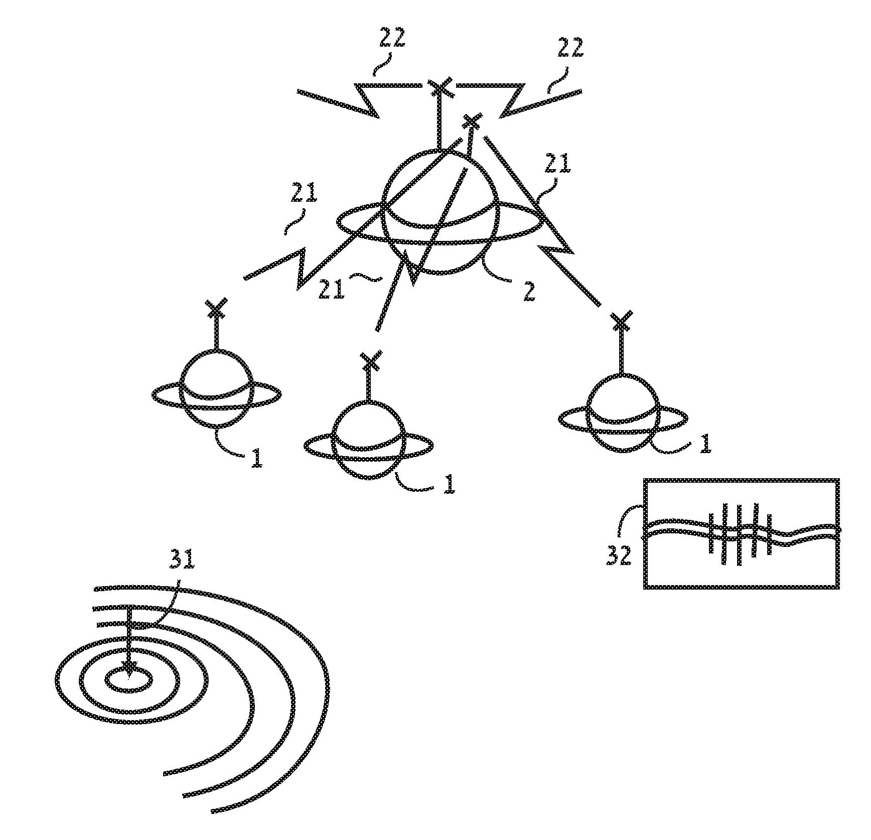
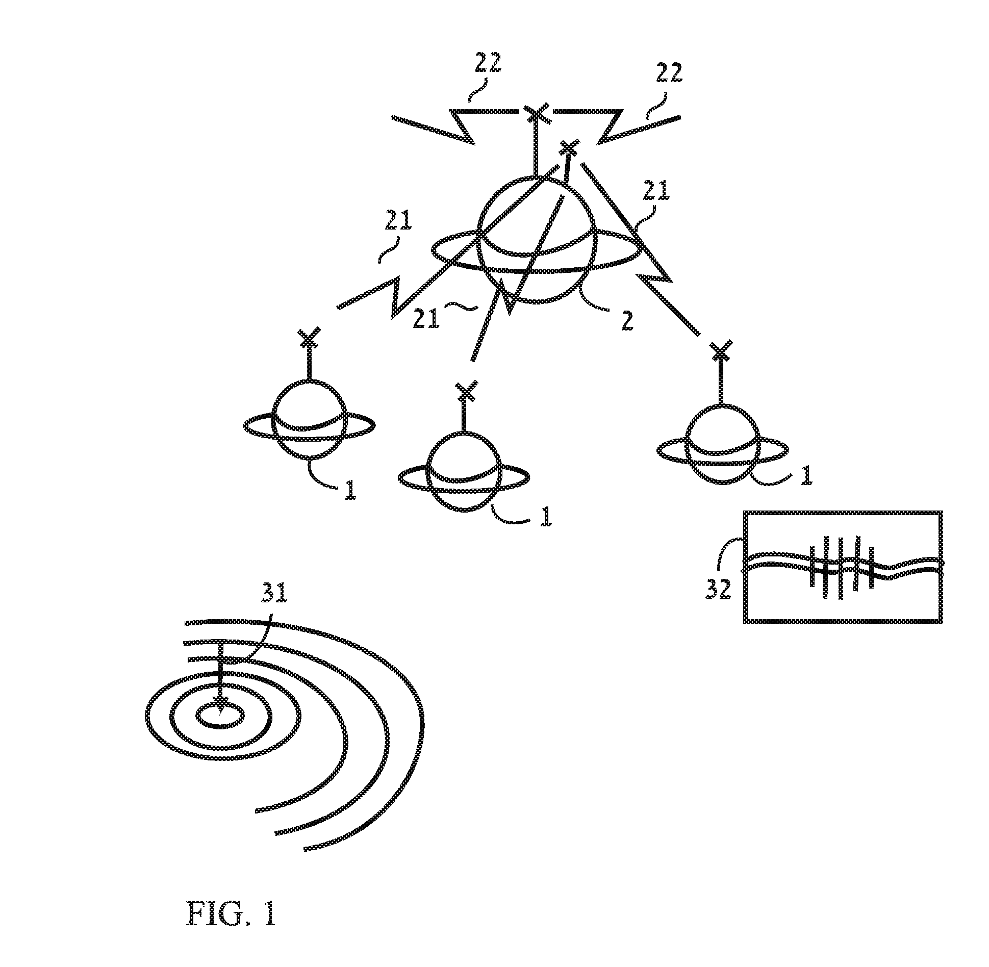
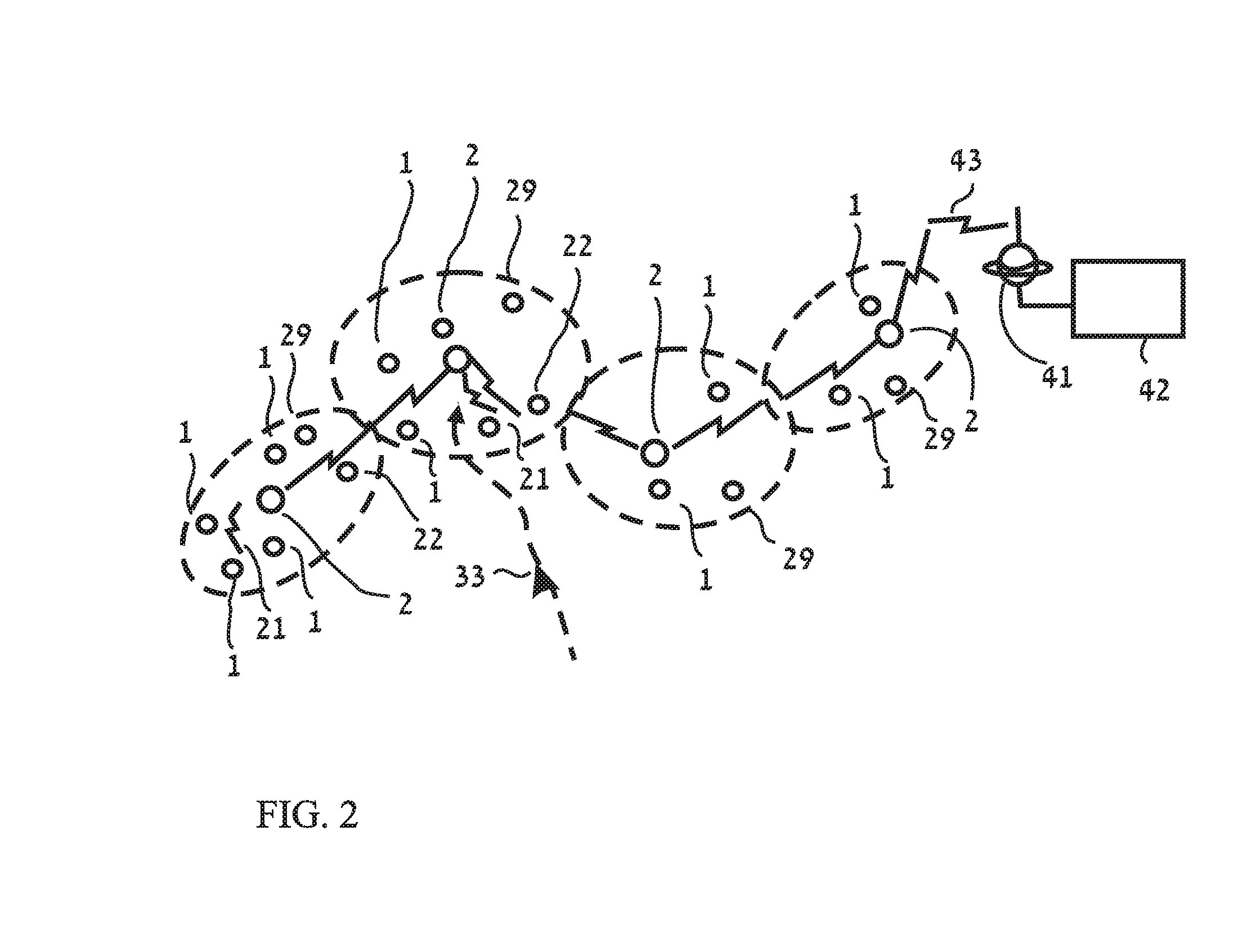
[0072]1. A modular, distributed system allows to protect a large area 11

[0073]2. A complete sensor enclosed in a ferromagnetic shield 17

[0074]3. The casing of a sensor unit has a directional aperture, structure or sail 19

[0075]4. Integrated, sealed, stand alone complete sensor with transmitter and battery 20

[0076]5. Use of cathodic voltage changes to detect offenders to, or protection faults in, oil, gas or other pipes and underground electrical cables 22

[0077]6. A Sophisticated algorithm for processing sensors data in a four dimensions 30

[0078]7. Detect leakage from pipe using multiple channels / inputs 36

[0079]8. A low power consumption, efficient communications protocol 39

1. A Modular, Distributed System Allows to Protect a La...


PUM


Abstract

A method for detecting leakage from a pipe uses multiple channels / inputs, wherein a low frequency range input measures seismic noises, and a high frequency range input measures cavitation noises. A leakage indication is issued if both the low frequency and high frequency noises are simultaneously detected. A Sophisticated algorithm for processing sensors data in a four dimensional space includes location and time, includes a method for detecting an intruder's path in a location and time space. A method for detecting unauthorized access to oil, gas or other pipes, by monitoring the protective cathodic voltage and detecting changes in the voltage which are indicative of a technical failure or a deliberate attack on the pipe.

Description

CROSS REFERENCE TO RELATED APPLICATIONS[0001]The present application claims priority from the patent application No. GB0715494.1 filed by the present applicant in Great Britain on 10 Aug. 2007, the application No. GB0718272.8 filed by the present applicant in Great Britain on 20 Sep. 2007, the application No. GB0722485.0 filed by the present applicant in Great Britain on 16 Nov. 2007, and the application No. US 12523534 filed by the present applicant in U.S.A. on 17 Jul. 2009, wherein US '534 is a U.S. National Stage under 35 USC 371 from PCT / IB2008 / 53212 filed on 11 Aug. 2008, all entitled “Monitoring system and method”.FIELD OF THE INVENTION[0002]The present invention relates to a method for detecting leakage from a pipe using multiple channels / inputs, wherein a low frequency range input measures seismic noises, and a high frequency range input measures cavitation noises.DESCRIPTION OF RELATED ART[0003]There is a need for a distributed system to protect a large area or an elongate...

Claims


Application Information

Patent Timeline
Patent Type & Authority Applications(United States)
IPC IPC(8): G01M3/24
CPCF17D5/06G01V1/181G01M3/243C23F13/22C23F2213/32
Inventor SAMUELSON, JOSEF
Owner SAMUELSON JOSEF
Why Eureka
Try Eureka