
Female part of a snap fastener

Inactive Publication Date: 2010-06-10
YKK CORP
View PDF18 Cites 4 Cited by
  • Summary
  • Abstract
  • Description
  • Claims
  • Application Information

AI Technical Summary

Benefits of technology

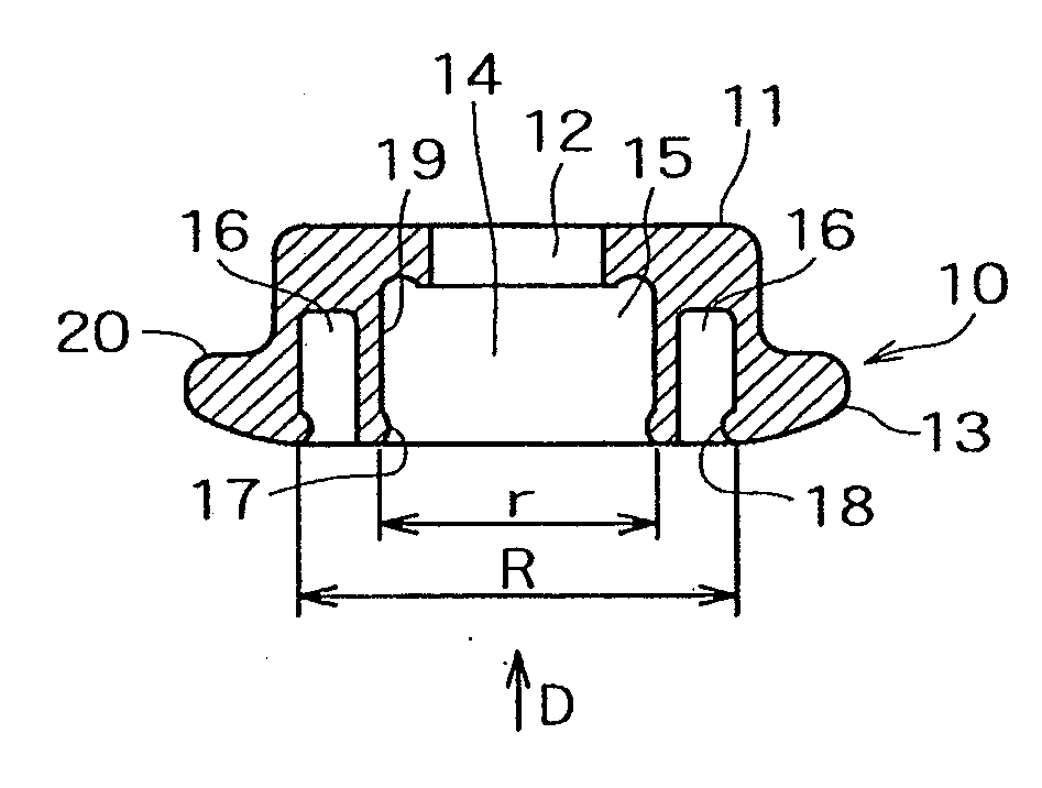
[0012]A very simple embodiment is achieved if an inner wall of the second reception area is at least partly identical with an outer wall of the first reception area.
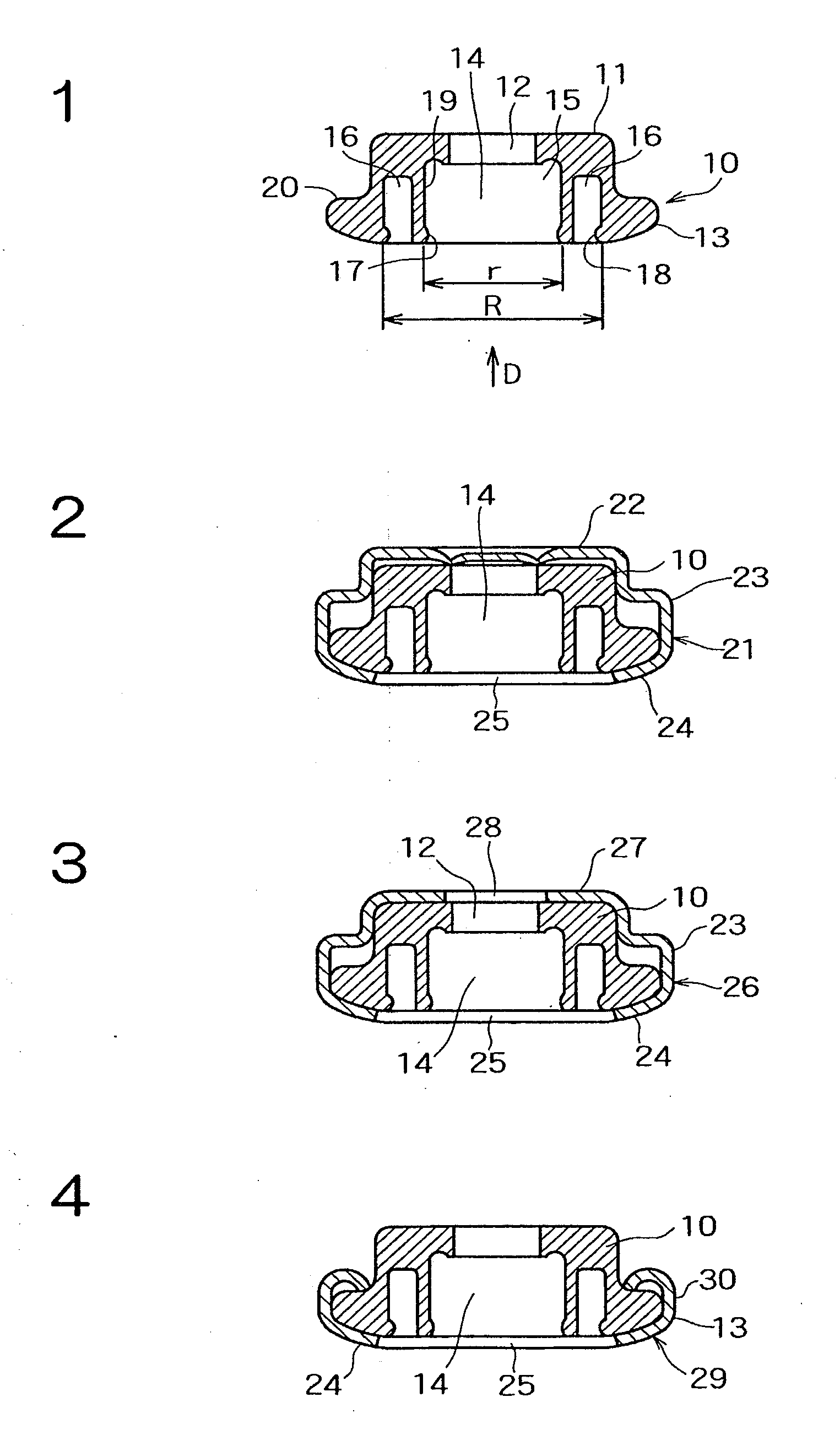
[0015]Additionally or alternatively, a kettle or cover can be provided as an outer envelope. Thus, higher separation forces can be obtained.
[0018]For fixing the snap fastener to a carder material or textile strip, a cap with a post and / or a 2-prong-cap can be used. Especially the 2-prong-cap permits highest separation forces or tensile strength.

Problems solved by technology

This involves considerable effort.

Method used


Image

  • Female part of a snap fastener
  • Female part of a snap fastener
  • Female part of a snap fastener

Examples


Embodiment Construction

[0032]FIG. 1 shows a main body 10 forming the core of a female part of a snap fastener according to an embodiment of the invention. The main body 10 of the female part is made of a plastic material and includes a base portion 11 disposed on the rear side of the main body 10 and having a through hole 12 formed therethrough through which posts of caps 34, 36 or a pair of prongs of a cap 38 can be inserted, as closely described hereinbelow, and a fitting portion 13 disposed on the front side of the main body 10 and adapted for fitting engagement with male parts. The fitting portion 13 is opened in its front side to thus have a fitting recess 14 formed therein for receiving fitting projections of the male parts when the fitting projections of the male parts are forced in the direction denoted by “D”. The fitting recess 14 has the through hole 12 formed in its bottom so that the fitting recess 14 communicates with the through hole 12. The fitting recess 14 and the through hole 12 are bot...


PUM


Abstract

The invention refers to a female part of a snap fastener including a first reception area (15) for locking a first male part (40). According to the invention, the female part further includes a second reception area (16) for locking a second male part (46, 47) is provided.

Description

FIELD OF THE INVENTION[0001]This invention refers to a female part of a snap fastener including a first reception area for locking a first male part. In this regard, a reception area is understood to be an area which is formed so that the male part locks with the female part when the male part is received in the reception area. Therefore, it can also be referred to a locking area since the reception of the male part involves the locking of the two parts.[0002]DESCRIPTION OF THE RELATED ART[0003]Female parts of the above-mentioned kind are known from the prior art. For example, they can be found on jackets or overcoats, the male part being attached to a hood belonging thereto. Another example is a bag having a female part and a cover serving for closing the bag and having a male part. Moreover, snap fasteners are used for various other purposes.[0004]Depending on the intended purpose, different demands are made on the snap fasteners. This applies to the opening force and / or the closi...

Claims


Application Information

Patent Timeline
IPC IPC(8): A44B17/00
CPCA44B17/0023Y10T24/45958A44B17/0076
Inventor PFERDEHIRT, THOMAS
Owner YKK CORP
Learn More