
Gain-Adjusting Apparatus For Optical Image Stabilizer And Method Thereof

a technology of optical image stabilizer and gain adjustment, which is applied in the direction of instruments, color television details, television systems, etc., can solve the problems of affecting the quality of the image, affecting the image quality,

Active Publication Date: 2010-06-03
ASIA OPTICAL INT LTD
View PDF3 Cites 4 Cited by
  • Summary
  • Abstract
  • Description
  • Claims
  • Application Information

AI Technical Summary

Benefits of technology

[0003]The objective of the present invention is to provide a gain-adjusting apparatus and method thereof applicable to the optical image stabilizer (OIS) of image processing equipment in order to avoid the abnormal sway status, i.e. panning effect, in the display area of the camera.
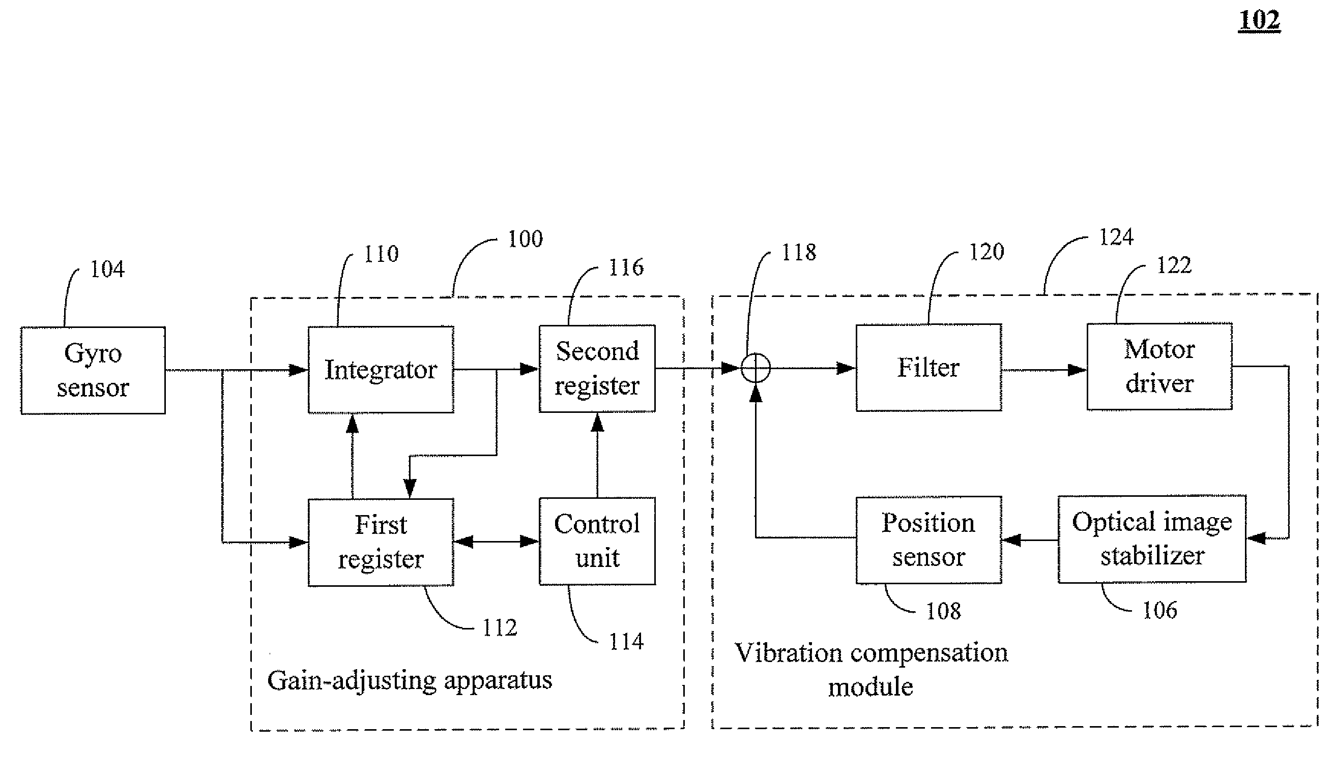
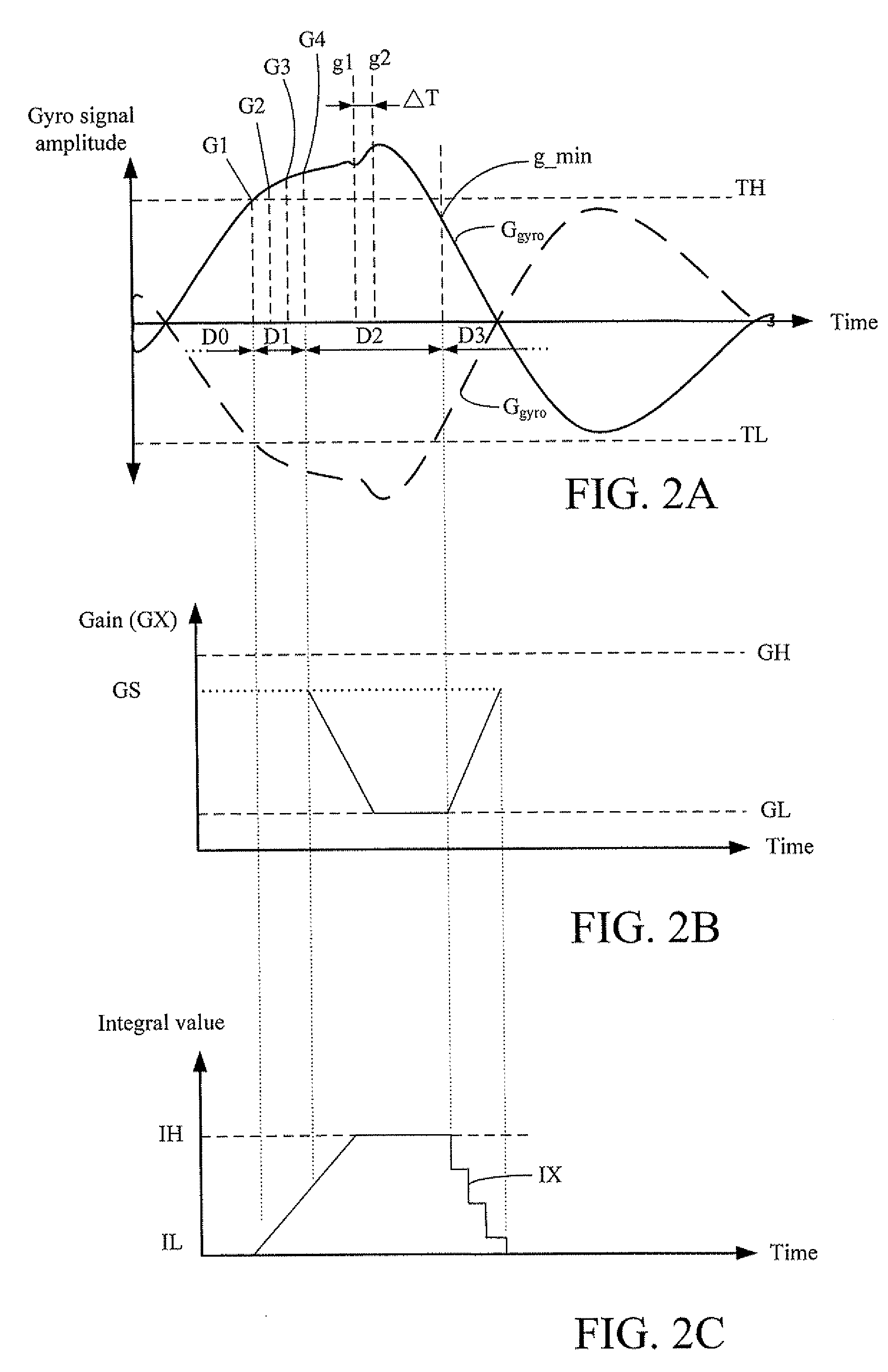
[0008]Specifically, the gain-adjusting apparatus in the present invention determines whether the image processing system is operated in the moving action based on the adjustment of the gyro signal (Sgyro) data. When the image processing system is operated in the moving action, the gain-adjusting apparatus enters moving action mode. Meanwhile, the control unit adjusts the gain value in the second register to modify the gyro signal (Sgyro) data and the vibration compensation module. The vibration compensation module decreases the vibration compensation according to the adjusted gyro signal (Sgyro) data so that the erroneous compensation of the vibration compensation module due to the moving action is avoided advantageously. In other words, the adjusted gyro signal (Sgyro) data which is inputted to the vibration compensation module allow the vibration compensation module to make no vibration decision and reduce the compensation range. Therefore, the panning effect of the image on the display area due to the activation of the optical image stabilizer (OIS) is solved.

Problems solved by technology

Meanwhile, since the optical image stabilizer (OIS) is activated by the camera, the camera compensates the optical image stabilizer (OIS), thereby resulting in an abnormal sway status in the preview display area of the camera and downgraded photo quality after the moving action stops at the and the predetermined position.

Method used


Image

  • Gain-Adjusting Apparatus For Optical Image Stabilizer And Method Thereof
  • Gain-Adjusting Apparatus For Optical Image Stabilizer And Method Thereof
  • Gain-Adjusting Apparatus For Optical Image Stabilizer And Method Thereof

Examples


Embodiment Construction

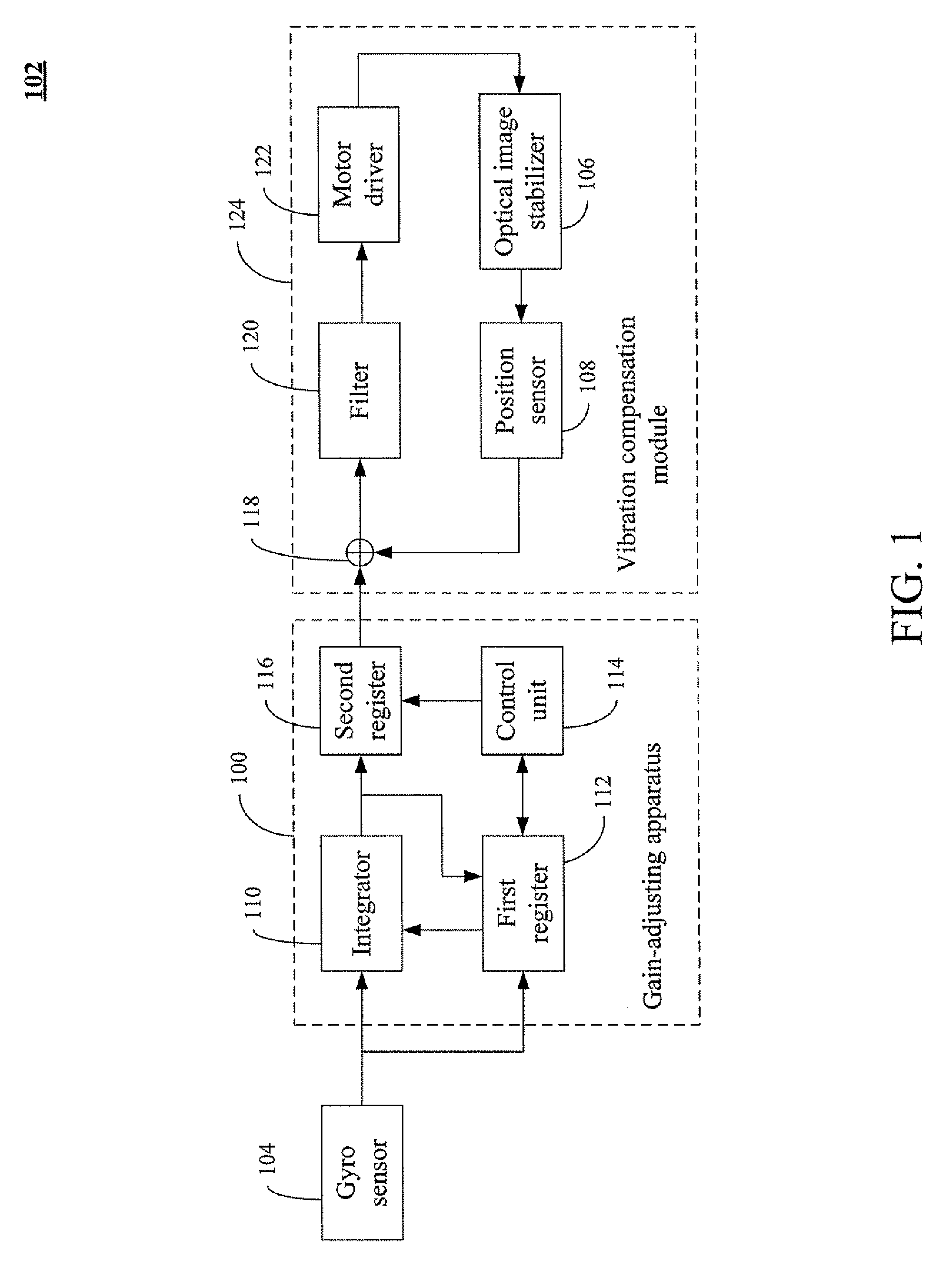
[0025]FIG. 1 is a schematic block diagram of an optical image stabilizer (OIS) 102 having a gain-adjusting apparatus 100 according to one embodiment of the present invention. The gain-adjusting apparatus 100 couples the gyro sensor 104 to the vibration compensation module 124. The gain-adjusting apparatus 100 outputs the gyro signal data having adjusted gain to the vibration compensation module 124. The gain-adjusting apparatus 100 is applicable to the optical image stabilizer (OIS) in the image processing equipment, such as digital camera, video camera and / or image processing system with the image stabilizer (OIS). The gain-adjusting apparatus 100 includes an integrator 110, a first register 112, a control unit 114 and a second register 116. In one embodiment, the gain-adjusting apparatus 100 is selected from a micro control unit (MCU), a digital signal processing, a central processing unit (CPU), a complex programmable logic device (CPLD), a field programmable gate array (FPGA), a...


PUM


Abstract

A gain-adjusting apparatus and method thereof are described. The gain-adjusting apparatus includes an integrator, a first register, a control unit, and a second register. The integrator integrates the gyro signal data to generate the integral data. The control unit is coupled to the first register and the second register, respectively. The control unit determines whether the gyro signal data is either greater than an upper gyro threshold or less than a lower gyro threshold to detect the gyro signal data and decrease the gain value stored in the second register.

Description

FIELD OF THE INVENTION[0001]The present invention relates to an adjusting apparatus and method thereof, and more particularly to a gain-adjusting apparatus and method thereof applicable to an optical image stabilizer.BACKGROUND OF THE INVENTION[0002]With the rapid development of information technology, the manufacture of consuming electronic products is becoming more and more diverse. For example, computer, liquid crystal display (LCD) TV, video camera, and digital camera are widely used. Particularly, the slim digital camera is portable for the user and the requirement of the display quality of capture photos and pixel standard are thus more and more increased. However, it is necessary to enhance the quality of the photos by increasing stability of the digital camera when the quality of captured photos may be degraded due to the vibration of the digital camera. Conventionally, when the camera is moved to a predetermined position and its internal optical image stabilizer (OIS) is tu...

Claims


Application Information

Patent Timeline
IPC IPC(8): H04N5/228
CPCH04N5/23248G02B27/644H04N23/68
Inventor LIN, YI-CHANG
Owner ASIA OPTICAL INT LTD
Learn More