
Exhaust emission control device

a technology of exhaust gas and control device, which is applied in the direction of electric control, machines/engines, transportation and packaging, etc., can solve the problems of insufficient removal of no/sub>x/sub>in the exhaust gas, and difficulty in ensuring the safety of carrying ammonia during running

Active Publication Date: 2010-06-03
HINO MOTORS LTD
View PDF11 Cites 12 Cited by
  • Summary
  • Abstract
  • Description
  • Claims
  • Application Information

AI Technical Summary

Benefits of technology

The present invention relates to an exhaust emission control device for vehicles. The invention aims to compactly arrange a particulate filter and a selective reduction catalyst while ensuring sufficient reaction time for the generation of ammonia from urea water. The invention solves the problem of limited space in vehicles by adding urea water between the particulate filter and the selective reduction catalyst and directing the exhaust gas from the particulate filter to the inlet end of the selective reduction catalyst in a forward fold-back manner. This ensures a long distance between the added position of the urea water and the selective reduction catalyst, allowing sufficient reaction time for the generation of ammonia. The invention also includes a communication passage for guiding the exhaust gas from the outlet end of the particulate filter to the inlet end of the selective reduction catalyst. Overall, the invention improves mountability on vehicles and reduces the space required for auxiliary machines such as a urea water tank.

Problems solved by technology

However, for automobiles, safety in carrying ammonia itself during running is difficult to ensure, so that in recent years, use of nontoxic urea water as reducing agent has been researched.
For exhaust emission control of the diesel engine, mere removal of NOx in the exhaust gas is insufficient; particulates (particulate matter) in the exhaust gas must be captured through a particulate filter.

Method used


Image

  • Exhaust emission control device
  • Exhaust emission control device
  • Exhaust emission control device

Examples


Embodiment Construction

[0028]An embodiment of the invention will be described in conjunction with drawings.

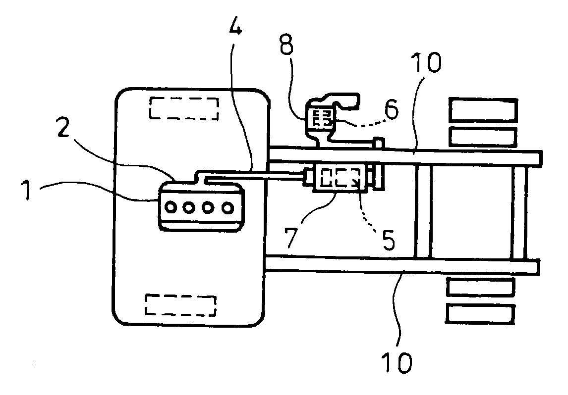
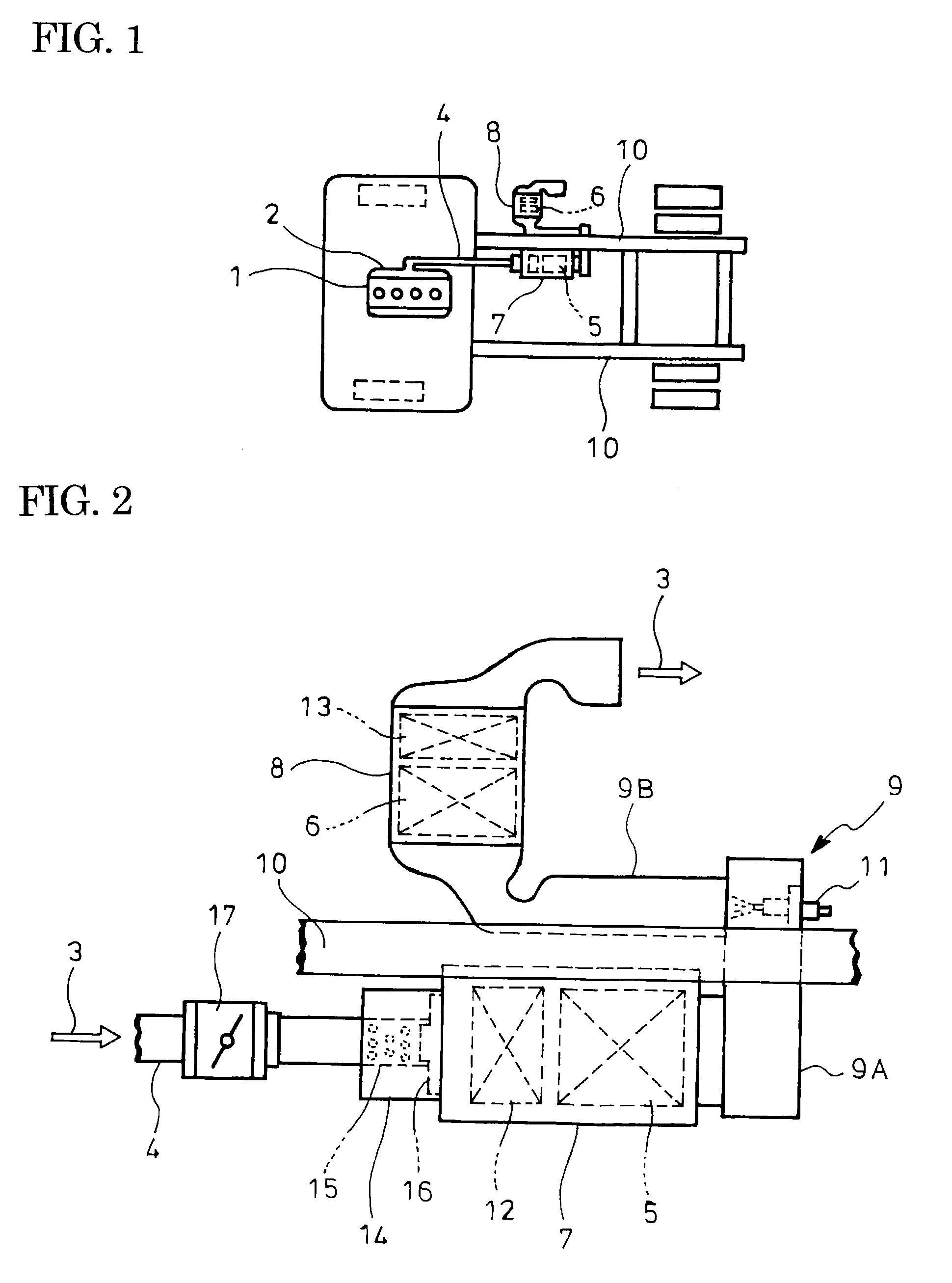
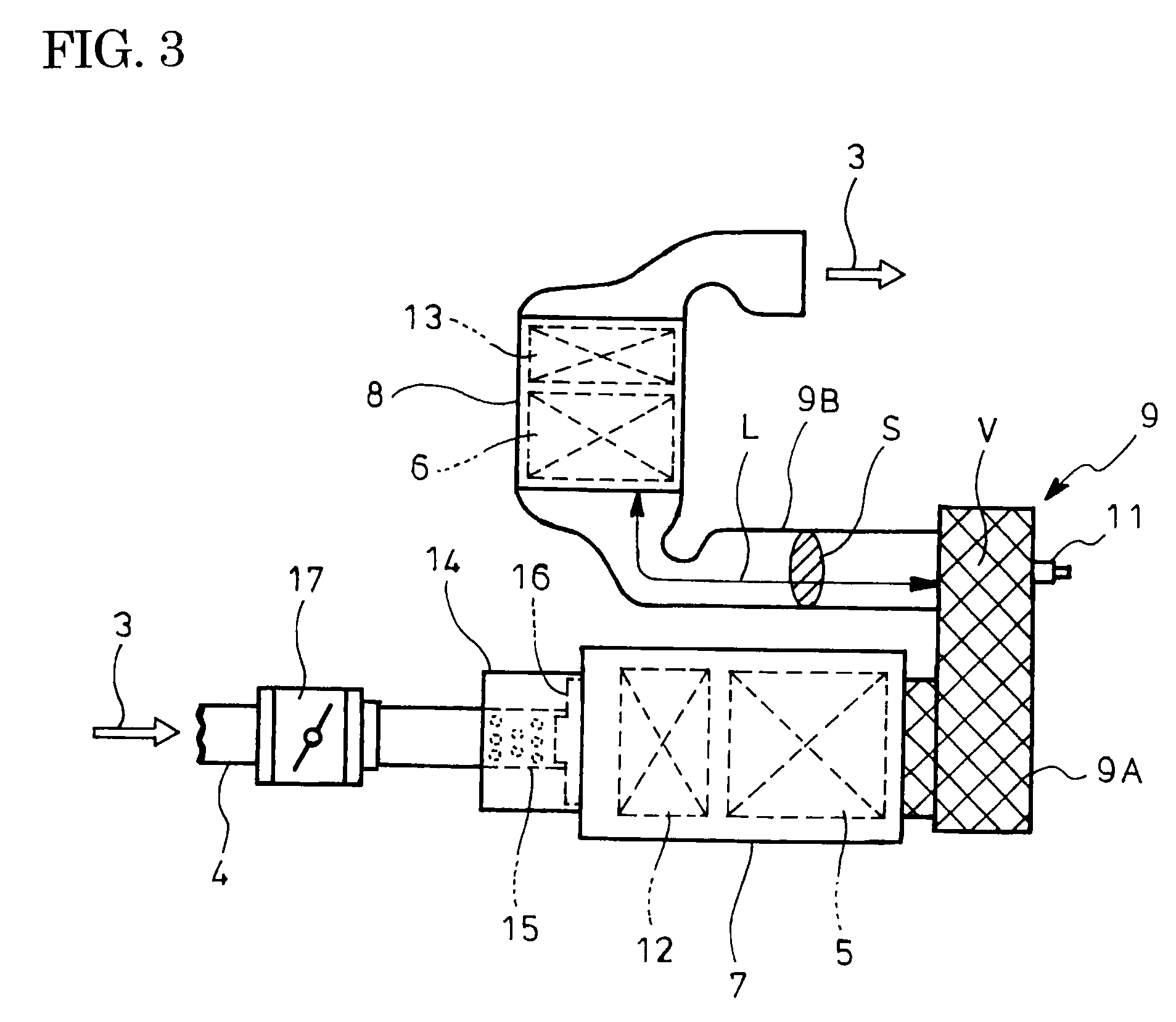
[0029]FIGS. 1-3 show the embodiment of the invention. In the exhaust emission control device of the embodiment, a particulate filter 5 for capture of particulates in exhaust gas 3 and a selective reduction catalyst 6 with a property capable of selectively reacting NOx with ammonia even in the presence of oxygen are encased by casings 7 and 8, respectively, and are incorporated in an exhaust pipe 4 through which the exhaust gas 3 from a diesel engine 1 flows via an exhaust manifold 2, the particulate filter 5 being longitudinally arranged along a frame 10 of a vehicle, the selective reduction catalyst 6 being arranged in a vicinity of the inlet end of the particulate filter 5 and directed to laterally outward of the vehicle.

[0030]Moreover, an outlet end of the particulate filter 5 is connected to the inlet end of the selective reduction catalyst 6 by a communication passage 9 such that the exhaust gas...


PUM


Abstract

The invention has its object to realize compact arrangement of particulate filter 5 and selective reduction catalyst 6 for improved mountability on a vehicle while a sufficient reaction time is ensured for generation of ammonia from urea water. In an exhaust emission control device with the filter 5 and the catalyst 6 capable of selectively reacting NOx with ammonia even in the presence of oxygen being incorporated in an exhaust pipe 4, urea water as reducing agent being addible therebetween, the filter 5 is arranged in a fore-and-aft direction of a vehicle and along a frame 10 of the vehicle. The catalyst 6 is arranged in a vicinity of an inlet end of the filter 5 and directed laterally outward of the vehicle. A communication passage 9 is arranged to guide the exhaust gas 3 discharged from an outlet end of the filter 5 to an inlet end of the catalyst 6 in a forwardly fold-back manner. A urea water adding injector 11 (urea water adding means) for addition of urea water is arranged midway of the passage 9.

Description

TECHNICAL FIELD [0001]The present invention relates to an exhaust emission control device.BACKGROUND ART [0002]Conventionally, some diesel engines have selective reduction catalyst incorporated in an exhaust pipe through which exhaust gas flows, said catalyst having a feature of selectively reacting NOx with a reducing agent even in the presence of oxygen. A required amount of reducing agent is added upstream of the reduction catalyst and is reacted on the catalyst with NOx (nitrogen oxides) in the exhaust gas to thereby reduce a concentration of the discharged NOx.[0003]In a field of industrial plant or the like with flue-gas denitration, it has been well known that ammonia (NH3) is effectively used as reducing agent to reduce and depurate NOx through reduction. However, for automobiles, safety in carrying ammonia itself during running is difficult to ensure, so that in recent years, use of nontoxic urea water as reducing agent has been researched.[0004]More specifically, when urea...

Claims


Application Information

Patent Timeline
Patent Type & Authority Applications(United States)
IPC IPC(8): F02D43/00F01N3/035F01N3/10
CPCB60K13/04F01N3/021F01N3/0253F01N3/035F01N3/106F01N13/009F01N13/08F01N2340/04F01N2590/08F01N2610/02Y02T10/24F01N3/2066Y02T10/12Y02A50/20
Inventor ENDO, HIROSHITAKAHASHI, NORIYUKI
Owner HINO MOTORS LTD
Learn More