Telescopic shaft

Active Publication Date: 2010-05-27
FUJI AUTOTECH
View PDF5 Cites 3 Cited by
  • Summary
  • Abstract
  • Description
  • Claims
  • Application Information

AI Technical Summary

Benefits of technology

[0007]By that the telescopic shaft comprises the characteristics of claim 1, the advantage of that the telescopic shaft shows the possibility of sliding of the balls as in the general ball-telescope, and the advantage of freedom from play between the parts of the telescope as in the prestressed-telescope as a mechanism in the telescope releases the prestress when the alteration in length of the telescopic shaft exceeds a predetermined length is attained. Thus is also attained the advantage of that narrow tolerances are not required over the entire length of the telescope.

Problems solved by technology

A problem with a telescope as mentioned above is that heavy demands for a long stroke of the telescopic shaft are put forward for trucks with tiltable cabs in order for the cab to be able to be tilted.
This causes problems with the long strokes that are required for tiltable cabs.
A problem with ordinary ball-telescopes where the balls may both roll and slide is that narrow tolerances are required over the entire stroke which causes problems with the long strokes that are required for tiltable cabs.

Method used


Image

  • Telescopic shaft
  • Telescopic shaft
  • Telescopic shaft

Examples


Embodiment Construction

[0018]Similar reference numerals are used for similar characteristic features in the different figures.

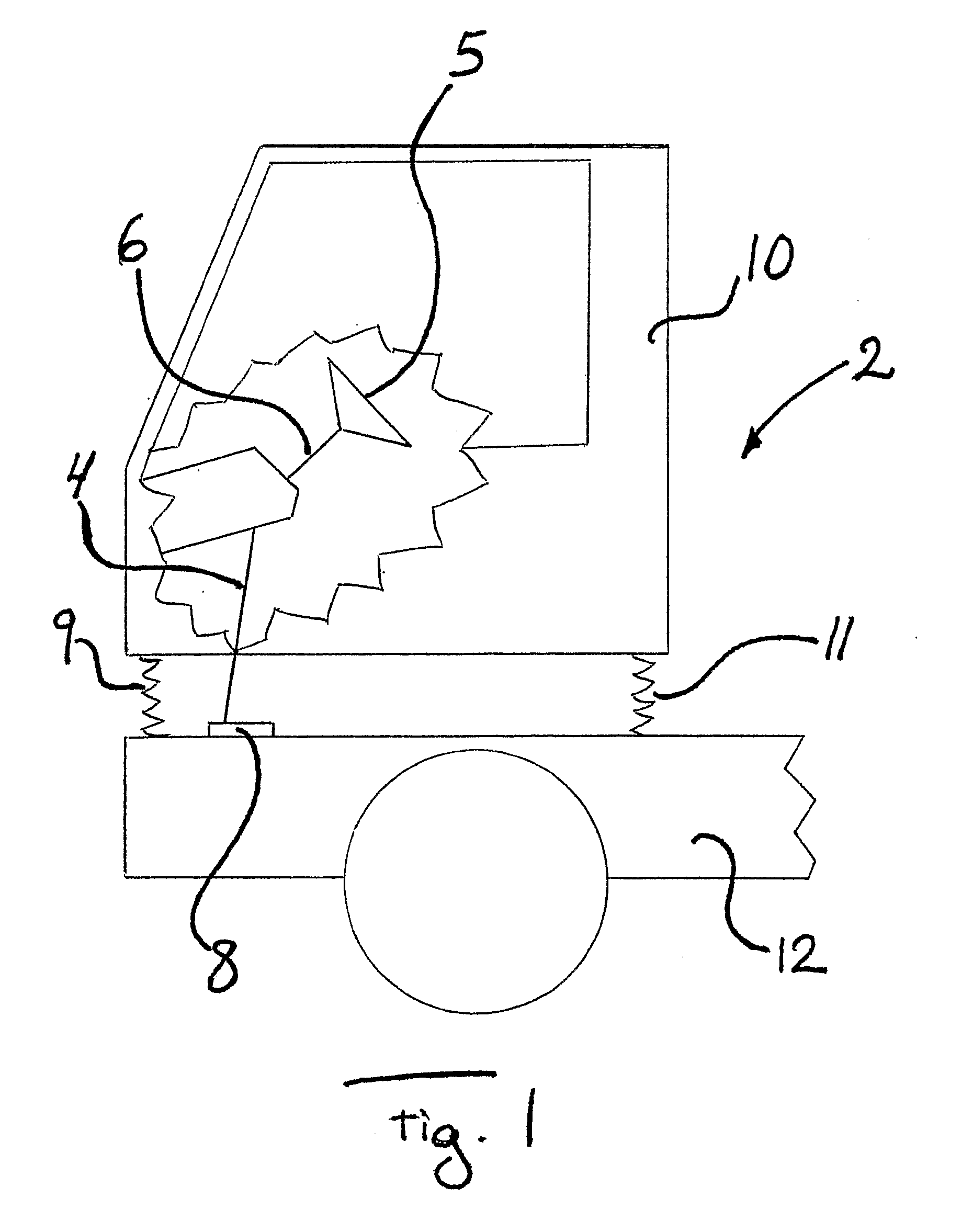
[0019]FIG. 1 shows schematically a view partly in section of a vehicle 2 with a lower steering shaft in the form of a telescopic shaft 4, where the telescopic shaft 4 is arranged between the steering wheel 5 of the vehicle 2 and the steering gear 8 of the vehicle 2, preferably between the upper steering shaft 6 of the vehicle 2 and the steering gear 8 of the vehicle 2. The steering wheel 5 is adjustable in relation to the cab 10 of the vehicle 2 in known manner and the steering gear 8 is fixed at the chassis 12 of the vehicle 2. The steering wheel 5 is preferably adjustable by that the upper steering shaft 6 is adjustable, which adjustment preferably is made when the vehicle 2 is stational. The cab 10 is further resiliently suspended in at least two points 9, 11 at the chassis 12 which results in that the telescopic shaft 4 alters its length when the cab 10 moves resiliently in rel...


PUM


Abstract

The invention relates to a telescopic shaft for vehicles comprising an inner shaft (14) axially movable in an outer shaft (16), where the telescopic shaft (4) comprises at least two rows (35, 37) of balls (36, 38) with at least one ball (36, 38) a row (35, 37) between the inner shaft (14) and the outer shaft (16), where a row (35) of balls (36) is arranged on at least one ball race (40) arranged against the inner shaft (14), where the ball race (40) is wedge shaped on its against the inner shaft (14) facing surface and that the telescopic shaft (4) comprises a prestress mechanism (46) which pushes the ball race (40) along a wedge unit (48) axially in relation to and radially in the direction against the outer shaft (16) whereby the telescopic shaft (48) is prestressed and that the prestress mechanism (46) is arranged to release the prestress when the alteration in length of the telescopic shaft (4) exceeds a predetermined length.

Description

TECHNICAL FIELD OF THE INVENTION[0001]The present invention relates to a telescopic shaft for vehicles.BACKGROUND[0002]Heavier vehicles, e.g. trucks and buses, usually have spring-suspended cabs that move in relation to the chassis of the vehicle whereby these vehicles have a lower steering shaft in the form of a telescopic shaft, which automatically may alter its length during the travel of the vehicle, between the steering wheel and the steering gear as the steering wheel is lockable in its axial direction to the cab of the vehicle whereas the steering gear is fixed to the chassis of the vehicle. The telescopic shaft may be of different kinds but usually comprises an outer shaft and an inner shaft that are axially movable in relation to each other but locked in relation to each other in the direction of rotation of the shaft in order to thereby be able to transfer torque from the steering wheel of the vehicle to the steering gear. General types of telescopic shafts are ball-telesc...

Claims


Application Information

Patent Timeline
IPC IPC(8): F16D3/06
CPCB62D1/16F16C3/035B62D1/20B62D1/185F16C2326/24
Inventor ERIKSSON, ULFFREDRIKSSON, HANS
Owner FUJI AUTOTECH
Why Eureka
Try Eureka