
Electromagnetic driver for a planar diaphragm loudspeaker

a technology of electromagnetic driver and diaphragm, which is applied in the direction of transducer diaphragm, transducer details, electrical transducers, etc., can solve the problems of unusable drive, local softening with irreversible shape changes, and inability to keep shape, etc., to achieve the effect of narrow tolerances, small axial) coil height, and minimal thickness of the planar diaphragm loudspeaker

Inactive Publication Date: 2007-03-22
HARMAN INT IND INC +1
View PDF8 Cites 2 Cited by
  • Summary
  • Abstract
  • Description
  • Claims
  • Application Information

AI Technical Summary

Benefits of technology

The invention is a driver for a planar diaphragm loudspeaker that is less sensitive to settings and can achieve a smaller coil height. It uses an electromagnetic driving principle and a symmetrical magnetic circle with an asymmetrical field distribution. The driver includes a soft magnetic core and an alternating field exciter that is magnetically coupled to the core. The driver is designed to produce a linear force or torque in response to the sound signal. The invention also provides a yoke that can pivot on the soft magnetic core and has small induction gaps to compensate for non-linear forces. The driver can be attached to the plate without any outside support and includes a spring element or a non-magnetic bearing to prevent shearing or pumping movements. The invention also provides a single pole planar diaphragm loudspeaker with two soft magnetic cores and two alternating field exciters for generating a magnetic alternating flux that depends on the sound signal.

Problems solved by technology

Even though electrodynamic drives develop sufficient power and deflection, they have however a setting problem in connection with the plate coupling.
The usual sandwich plates made of different types of bonded materials are very light and unbending, but do not keep their shape over time.
Beyond that thermal stresses during operation lead to local softening with irreversible shape changes.
This can cause the voice coil to touch the walls of the annular gap in the magnet system and thereby render the drive unusable.
The operation of bending wave radiators has the further problem in which the usual drivers perform an undesirable pumping movement, because bending without “pumping” is desirable in bending wave radiators, as opposed to piston radiators.
Furthermore the drivers named so far do not permit any edge excitation during bending wave operation.
Even though the electrodynamic drivers known for example from U.S. Pat. No. 4,392,027 or DE 198 21 860, which exert power normal to the plate surface, can be cost-effectively produced, they have the disadvantage of a relatively large construction depth and need a relatively large surface for support by an external bead.
Furthermore it is precisely the edge area of the plate which creates a problem for the long-term stable adjustment of the voice coil position with respect to the external bead.

Method used


Image

  • Electromagnetic driver for a planar diaphragm loudspeaker
  • Electromagnetic driver for a planar diaphragm loudspeaker
  • Electromagnetic driver for a planar diaphragm loudspeaker

Examples


Embodiment Construction

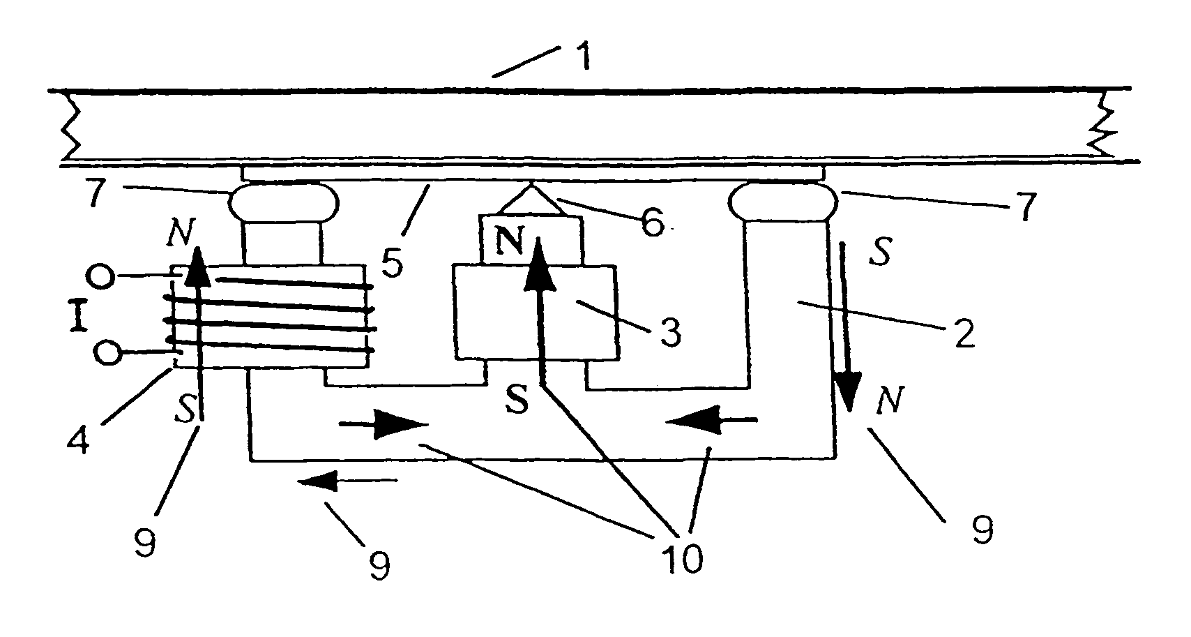
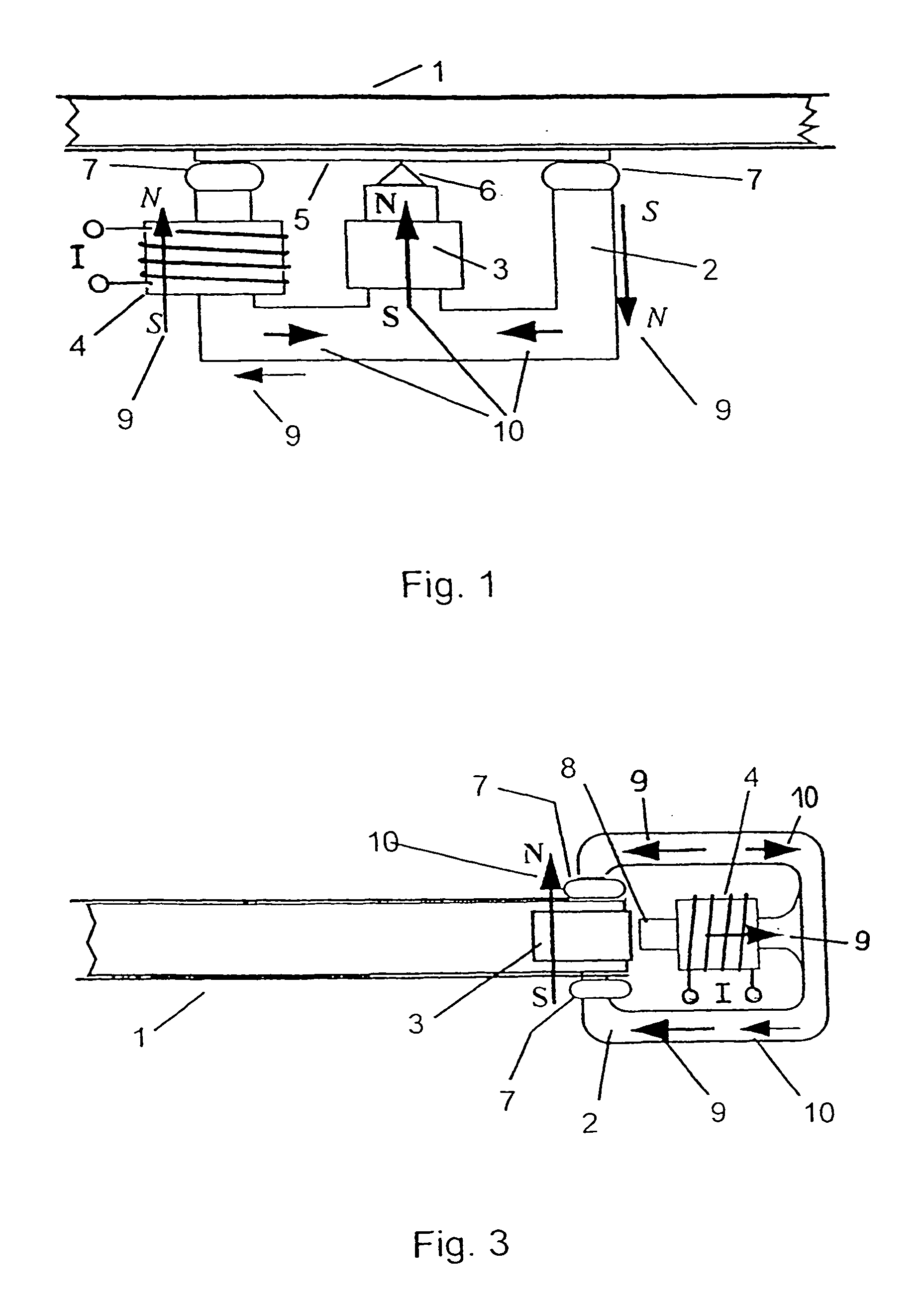
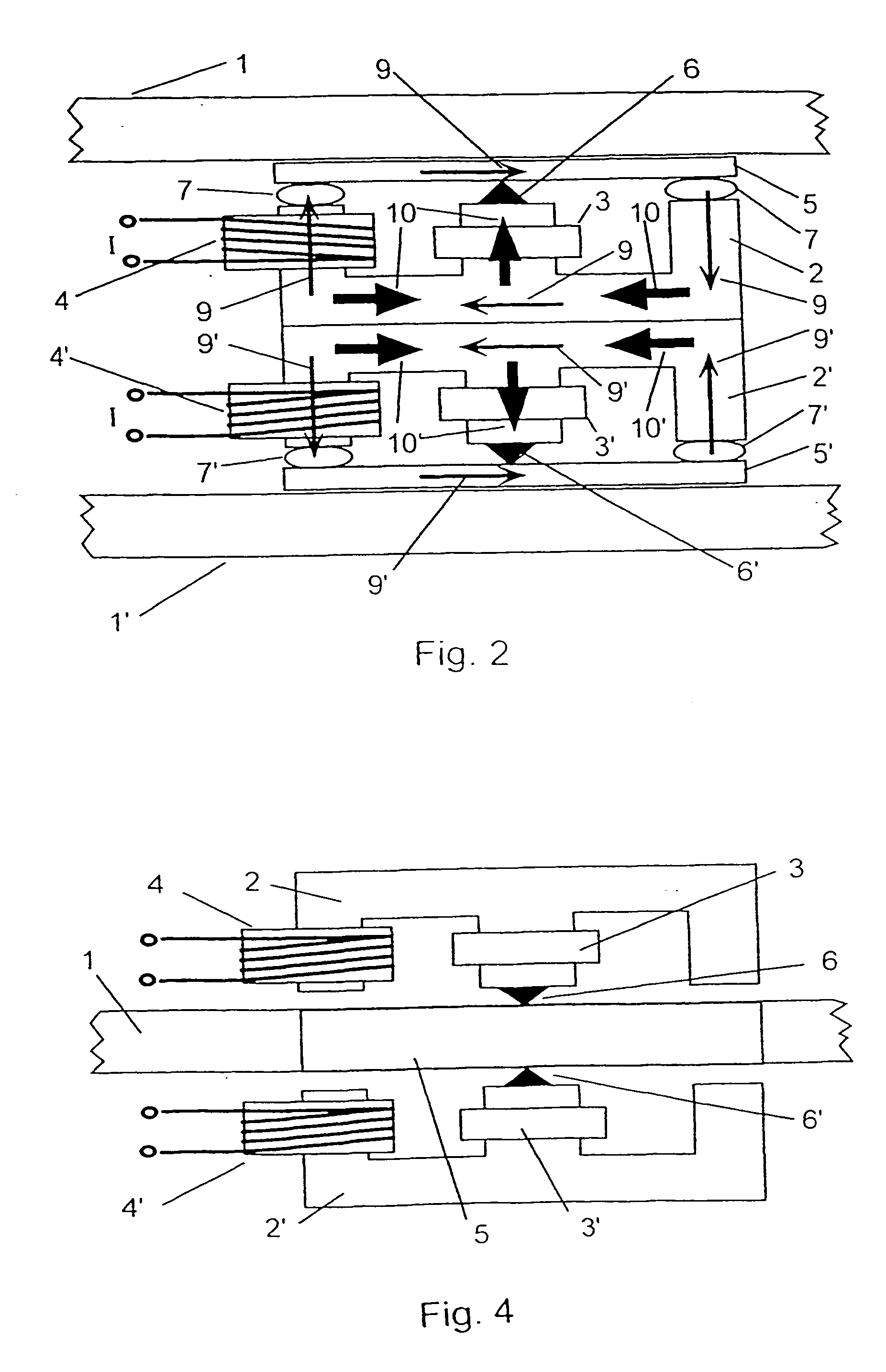
[0035]FIG. 1 shows an electromagnetic inertial torque driver according to the invention which is coupled to a sandwich diaphragm 1 resulting in a multiresonance planar diaphragm loudspeaker. A soft magnetic E-shaped pole core 2 (made of ferrite material for example) with two outer legs and a central leg is an alternating field exciter equipped with a motionless driver coil 4 on one of the outer legs. It is also possible to install a driver coil on each of the outer legs and have the same current flowing through it. In the embodiment of FIG. 1 the premagnetization takes place in the central leg by means of a constant field exciter, such as for example a coil having direct current flowing though it, or by a permanent magnet 3. The direction of the respective constant field vector 10 is oriented toward the central leg, where the polarity (N-S or S-N) is arbitrary. A sonic frequency alternating current I flows through the driver coil 4 and generates an alternating field vector 9. This f...


PUM


Abstract

The invention relates to an electromagnetic driver comprising a soft magnetic core in the form of an E with three legs and a back, an alternating field driver, magnetically coupled to the soft magnetic core, for generating an alternating magnetic field in the soft magnetic core, depending upon a sound signal, a constant field driver magnetically coupled to the soft magnetic core for generation of a constant magnetic field in the soft magnetic core, a soft magnetic element for coupling to the plate of the planar diaphragm loudspeaker, lying opposite the back and magnetically closing the legs across at least one small induction gap, whereby the constant field and the alternating field are asymmetrically superimposed such that a resulting force, or a resulting torque on the soft magnetic element, is proportional to the sound signal.

Description

CROSS REFERENCE TO RELATED APPLICATIONS [0001] This application is a continuation of U.S. patent application Ser. No. 10 / 432,487 which was filed on May 21, 2003 which in turn is an application for entry into the U.S. national phase under §371 for International Application No. PCT / EP01 / 11184 having an international filing date of Sep. 26, 2001, and from which priority is claimed under all applicable sections of Title 35 of the United States Code including, but not limited to, Sections 120, 363 and 365(c), and which in turn claims priority under 35 USC §119 to German Patent Application No. DE10058104.8 filed on Nov. 23, 2000.TECHNICAL FIELD [0002] The invention concerns an electromagnetic driver for a planar diaphragm loudspeaker. BACKGROUND OF THE INVENTION [0003] Electromagnetic transducers are known in general for example from WO 95 / 14363 or in particular with linearization of the characteristic curve by inserting a permanent magnet, for example from EPO774 880 or from U.S. Pat. No...

Claims


Application Information

Patent Timeline
Patent Type & Authority Applications(United States)
IPC IPC(8): H04R9/06H04R7/04H04R11/02
CPCH04R11/02H04R7/045
Inventor BACHMANN, WOLFGANGREGL, HANS-JURGENKRUMP, GERHARDZIGANKI, ANDREAS
Owner HARMAN INT IND INC
Learn More