Heat exchange catheter and method of use

a technology of heating catheter and urethra, which is applied in the field of urological warming and cooling devices, can solve the problems of strong thermal gradient in the prostatic urethra, uneven heating effect, and insufficient warm to protect the external sphincter from freezing, so as to prevent urethral sloughing, enhance the fluid dynamic properties of the catheter, and increase the effect of turbulen

Active Publication Date: 2009-11-24
VARIAN MEDICAL SYSTEMS
View PDF49 Cites 22 Cited by
  • Summary
  • Abstract
  • Description
  • Claims
  • Application Information

AI Technical Summary

Benefits of technology

[0014]The heat exchange catheter is particularly useful as a warming catheter for prostatic cryosurgical procedures where cryosurgical probes are used and it is desired to maintain the temperature of the urethral tissues to prevent urethral sloughing.
[0015]Offset positioning of the inner balloon, in contrast to any coaxial relationship of this inner balloon to the outer balloon and the discharge tube (such as disclosed in U.S. Pat. Nos. 5,437,673 and 5,624,392) has certain advantages. An offset relationship enhances the fluid dynamic properties of the catheter. It provides an increased turbulence, which, in turn, maximizes the heat exchange efficiency.
[0016]Furthermore, this offset positioning provides the ability to have a discharge tube of minimal thickness and thus enhanced flexibility, which is important, for example, for application in the urethra in which the catheter must be able to bend around the pubic bone when inserted through the urethra.

Problems solved by technology

However, other necrosed tissue may slough off and pass through the urethra, often causing undesirable blockage.
As a result, the urethral tissue near the bladder neck sphincter (near the hot water outlet) is heated more than the urethral tissue near the external sphincter, creating a strong thermal gradient in the prostatic urethra and an uneven heating effect.
By the time the hot water reaches the external sphincter, it may have lost so much heat to the upper region of the urethra that it is not warm enough to protect the external sphincter from freezing.

Method used


Image

  • Heat exchange catheter and method of use
  • Heat exchange catheter and method of use
  • Heat exchange catheter and method of use

Examples


Embodiment Construction

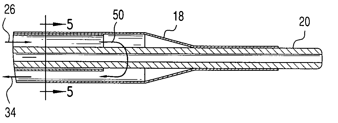
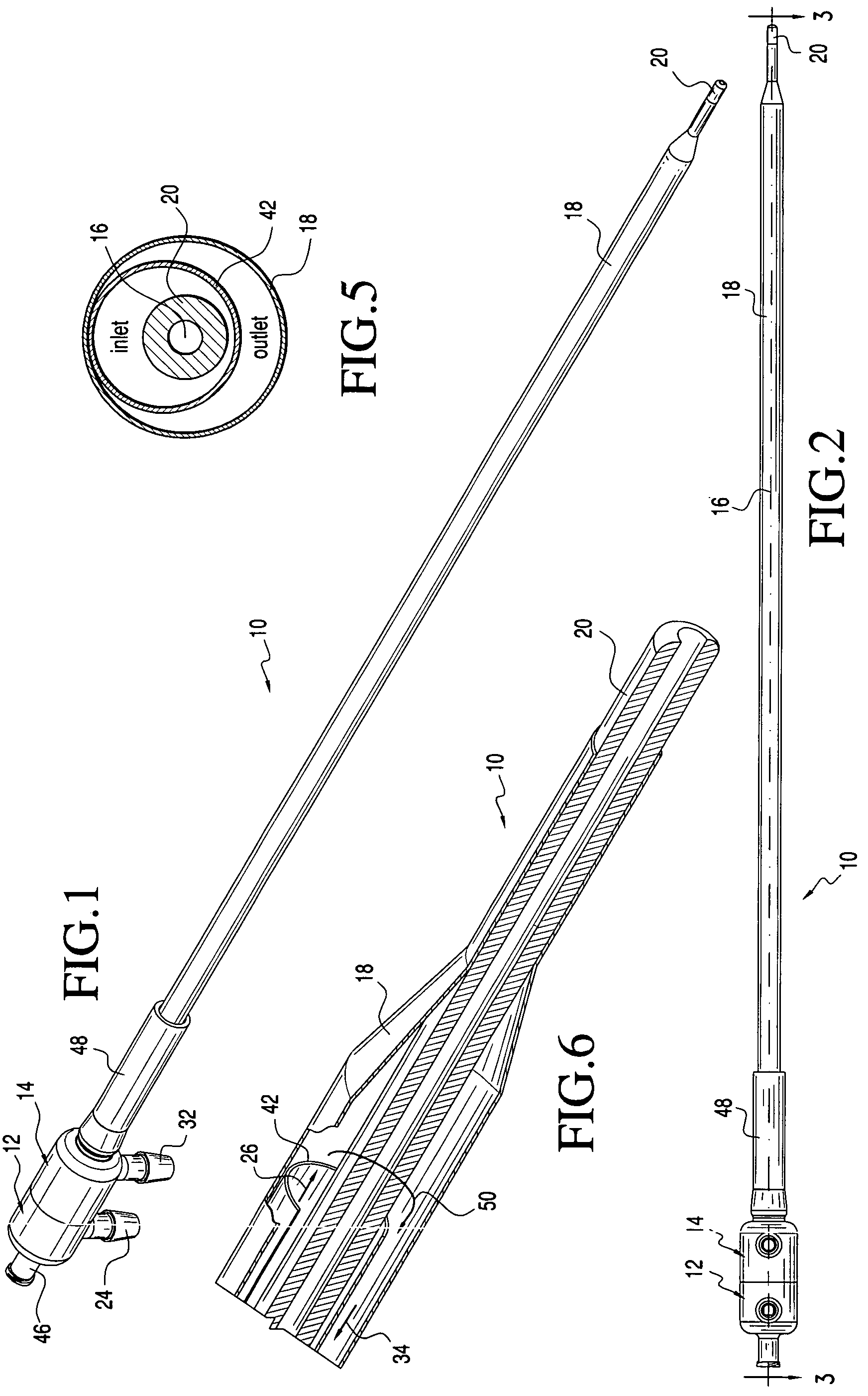
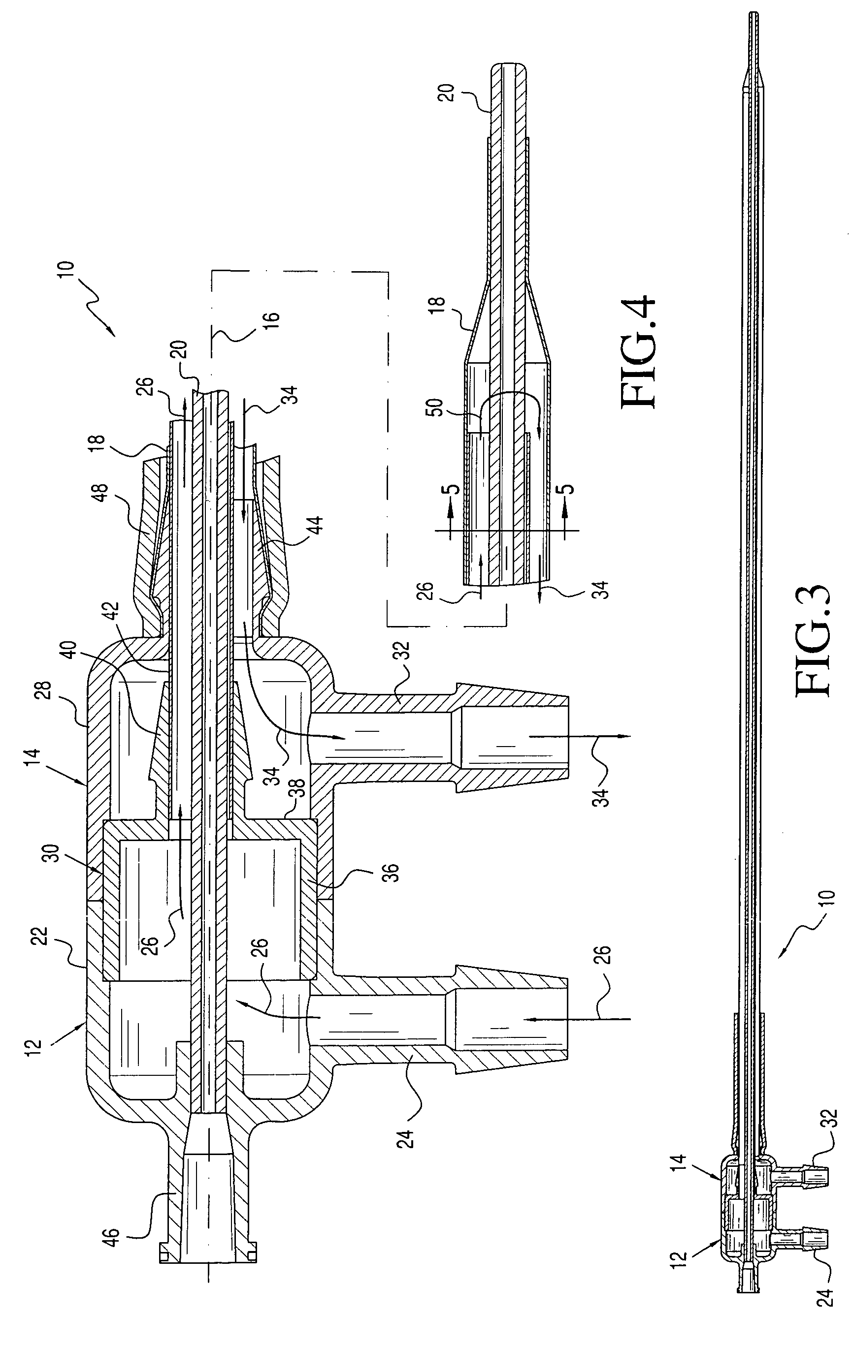
[0028]Referring now to the drawings and the characters of reference marked thereon, FIGS. 1-6 illustrate a first embodiment of the heat exchange catheter of the present invention, designated generally as 10. The catheter 10 includes an inflow housing assembly, designated generally as 12 and an outflow housing assembly, designated generally as 14. The generally cylindrical housing assemblies 12, 14 are coupled to each other and are serially positioned along a common housing assembly central axis 16. An outer balloon 18 projects from the distal end of the outflow housing assembly 14. A discharge tube 20 is also positioned along the central axis 16 and extends beyond the end of the outer balloon 18.

[0029]As best seen with reference to FIG. 4, the inflow housing assembly 12 includes an inflow housing main section 22 and an inflow housing inlet section 24 coupled to the inflow housing main section for providing an inlet flow of warming fluid to the inflow housing main section. The inflow...


PUM


Abstract

An inlet flow of heat exchange fluid flows from an inflow housing inlet section, and through an inflow housing main section. It then flows through an inlet fluid passageway formed between an inner balloon and a discharge tube. The flow continues around a distal end of the inner balloon, thus becoming an outlet flow of the heat exchange fluid which is directed through an outlet fluid passageway formed between the inner balloon and an outer balloon, then through an outflow housing main section and finally discharged through an outflow housing outlet section. The inner balloon is in a position offset from the central axis of the catheter. The offset relationship enhances the fluid dynamic properties of the catheter. It provides an increased turbulence, which, in turn, maximizes the heat exchange efficiency.

Description

BACKGROUND OF THE INVENTION[0001]1. Field of the Invention[0002]The present invention relates to urological warming and cooling devices and more particularly to a warming catheter and method of warming the urethra of a patient during ablative surgery. The apparatus is particularly useful in cryosurgery to prevent damage to tissues surrounding a surgical site from the extremely cold temperatures employed therein. The apparatus is especially useful during transperineal cryoablation of the prostate gland in human males to maintain the temperature of the urethral tissues and thereby prevent urethral sloughing. The apparatus may also have utility where it is desired to lower the temperature of surrounding tissues, such as during laser ablation.[0003]2. Description of the Related Art[0004]Cryosurgical probes are used to treat a variety of diseases. The cryosurgical probes quickly freeze diseased body tissue, causing the tissue to die after which it will be absorbed by the body, expelled b...

Claims


Application Information

Patent Timeline
Patent Type & Authority Patents(United States)
IPC IPC(8): A61F7/12
CPCA61F7/12A61F2007/126A61F7/123
Inventor DUONG, THACHEUM, JAY J.LIU, JENNY C.
Owner VARIAN MEDICAL SYSTEMS
Why Eureka
Try Eureka