
Valve drive of an internal combustion engine

a technology of internal combustion engine and valve drive, which is applied in the direction of engine components, machines/engines, mechanical equipment, etc., can solve problems such as valve drive malfunctions

Active Publication Date: 2010-05-27
DR ING H C F PORSCHE AG
View PDF1 Cites 21 Cited by
  • Summary
  • Abstract
  • Description
  • Claims
  • Application Information

AI Technical Summary

Benefits of technology

[0008]In accordance with aspects of the present invention, it is proposed that a guide element be assigned to the end of the actuating pin which can be introduced into the stroke curves of the stroke profile, wherein the guide element is rotatably supported on the end of the actuating pin, namely, in such a way that the guide element can rotate or pivot around the axis of the actuating pin. By means of a guide element such as this, it is possible to prevent the actuating pin from becoming jammed in the intersection area as it travels through the area where the stroke curves intersect. It is also possible to prevent the actuating pin from leaving the prescribed stroke curve of the stroke profile and unintentionally arriving in the other stroke curve of the stroke profile as it passes through the intersection area.

Problems solved by technology

When, in the case of the valve drive of DE 101 48 178 A1, an actuating pin travels through the area where the intersecting stroke curves intersect, the valve drive can malfunction, because there is the danger that the actuating pin can become jammed in the intersection area or, upon traveling through the intersection area, it can arrive in the area of the wrong stroke curve.
This is disadvantageous.

Method used


Image

  • Valve drive of an internal combustion engine
  • Valve drive of an internal combustion engine
  • Valve drive of an internal combustion engine

Examples


Embodiment Construction

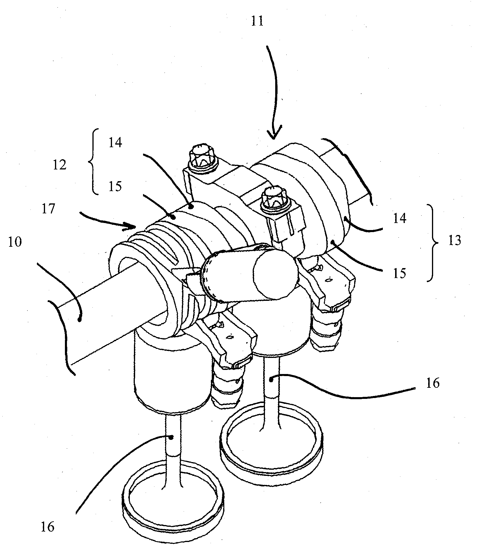
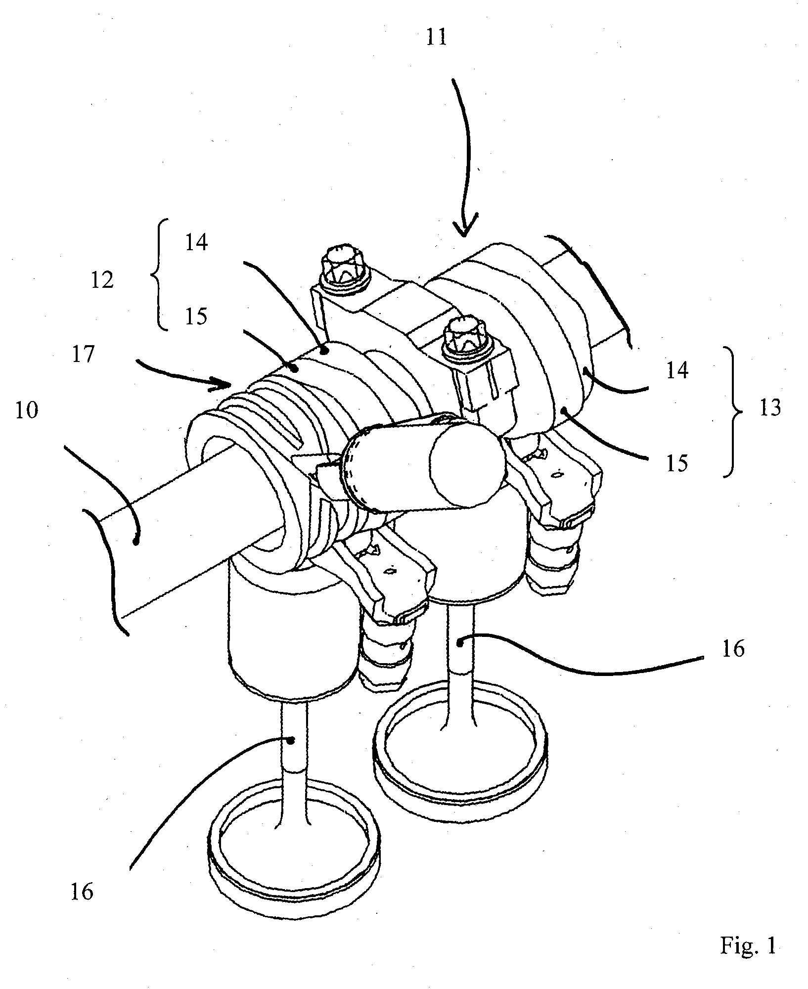
[0016]FIG. 1 shows part of an inventive valve drive of an internal combustion engine in the area of a cam piece 11, guided rotatably but with freedom of axial displacement on a camshaft 10, wherein the cam piece 11 comprises two cams 12, 13. Each cam 12, 13 of the axially displaceable cam piece 11 on the camshaft 10 has, in the exemplary embodiment shown here, two cam faces 14, 15, which are positioned one behind the other, i.e., next to each other, in the axial direction of the camshaft 10.

[0017]Each cam 12, 13 serves to actuate a gas-exchange valve 16, wherein the cams 12, 13 convert a rotational movement of the camshaft 10 into a stroking movement of the associated gas-exchange valve 16. An amplitude and / or phase position of the stroking movements of the gas-exchange valves 16 depends on the axial position which the cam piece 11 assumes on the camshaft 10 and on which cam face 14 or 15 of the cams 12, 13 serves to actuate the associated gas-exchange valve 16.

[0018]According to FI...


PUM


Abstract

A valve drive of an internal combustion engine, with a camshaft including cams for actuating gas-exchange valves, wherein at least one cam, which includes several cam faces, is guided nonrotatably but with freedom of axial movement on the camshaft; wherein a stroke profile, which cooperates with an actuating pin for the axial displacement of the cam or cam piece, is assigned to the associated axially displaceable cam or an axially displaceable cam piece comprising several cams; and wherein the stroke profile of the axially displaceable cam or cam piece in question includes intersecting stroke curves. A guide element is assigned to the end of the actuating pin which can be introduced into the stroke curve of the stroke profile of the associated axially displaceable cam or cam piece, this guide element being supported in such a way that it can rotate or pivot around the axis of the actuating pin.

Description

CROSS REFERENCE TO RELATED APPLICATIONS[0001]This U.S. patent application claims priority to German Application DE 10 2008 060 167.5, filed Nov. 27, 2008, which is incorporated by reference herein in its entirety.FIELD OF THE INVENTION[0002]The present invention pertains to a valve drive of an internal combustion engine.BACKGROUND OF THE INVENTION[0003]EP 0 798 451 B1 discloses a valve drive of an internal combustion engine with a camshaft, to which several cams, each of which actuates a gas exchange valve, are assigned. Each cam is supported nonrotatably on the camshaft but with the freedom to shift axially, wherein each cam comprises several cam faces arranged next to each other in the axial direction of the camshaft. Depending on the axial position of the cams on the camshaft, one of the cam faces of each cam is active and converts a rotational movement of the camshaft into stroking movements of a gas exchange valve. According to EP 0 798 451 B1, a stroke profile is formed on eac...

Claims


Application Information

Patent Timeline
Patent Type & Authority Applications(United States)
IPC IPC(8): F01L1/34
CPCF01L1/185F01L13/0036F01L2820/031F01L2800/12F01L2013/0052
Inventor TALAN, GEORGBATZILL, MANFREDSCHWARZENTHAL, DIETMAR
Owner DR ING H C F PORSCHE AG
Learn More