Automatic throttle roll angle compensation

a technology of automatic throttle roll and angle compensation, applied in the field of aircraft, can solve the problems of aircraft slowness, increased drag, and decreased wing li

Active Publication Date: 2010-05-20
THE BOEING CO
View PDF29 Cites 16 Cited by
  • Summary
  • Abstract
  • Description
  • Claims
  • Application Information

AI Technical Summary

Problems solved by technology

With the increase in the angle of attack, drag also may be increased.
Without sufficient thrust, the aircraft may slow, further decreasing the wing lift.
Further, the aircraft also may change altitude.
These changes in the movement of the aircraft are often undesirable during a turn.
These types of throttle systems for generating thrust are typically inaccurate for roll maneuvers that are above around 25 to around 30 degrees.

Method used


Image

  • Automatic throttle roll angle compensation
  • Automatic throttle roll angle compensation
  • Automatic throttle roll angle compensation

Examples


Embodiment Construction

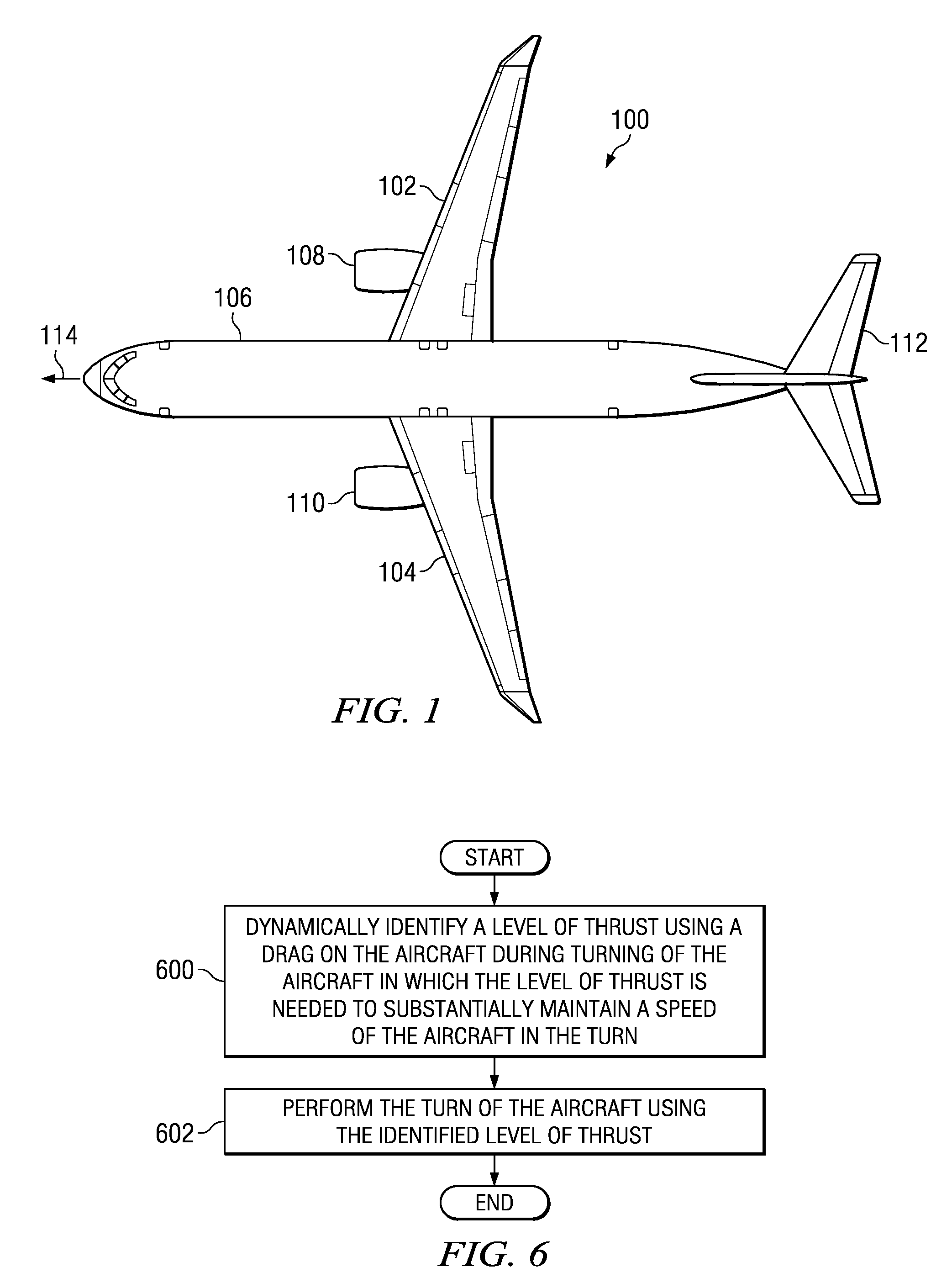
[0020]With reference now to the figures and, in particular, with reference to FIG. 1, a diagram of an aircraft is depicted in accordance with an advantageous embodiment. Aircraft 100 is an example of an aircraft in which automatic control with roll angle compensation may be implemented. In particular, hardware and / or software may be implemented within aircraft 100 to identify a maximum safe roll angle for level flight with a reference load factor.

[0021]In this illustrative example, aircraft 100 has wings 102 and 104 attached to fuselage 106. Aircraft 100 also includes engine 108, engine 110, and horizontal stabilizer 112. Aircraft 100 may make a number of different types of maneuvers. Some maneuvers may be lateral maneuvers in which aircraft 100 remains at the same altitude. In other words, lateral maneuvering is maneuvering on a horizontal plane, while vertical maneuvering is up and down movement relative to a vertical plane. Aircraft 100 also may perform vertical maneuvers in whic...


PUM


Abstract

A method, apparatus, and computer program product for adjusting a thrust for an aircraft. A level of thrust is dynamically identified using a drag on the aircraft needed to substantially maintain a speed of the aircraft in a turn to form an identified level of thrust during turning of the aircraft. The turn of the aircraft is performed using the identified level of thrust.

Description

GOVERNMENT LICENSE RIGHTS[0001]This invention was made with Government support under contract number N00019-04-C-3146 awarded by the United States Navy. The Government has certain rights in this invention.BACKGROUND INFORMATION[0002]1. Field:[0003]The present disclosure relates generally to aircraft and, in particular, to a method and apparatus for managing the operation of an aircraft. Still more particularly, the present disclosure relates to a method and apparatus for managing thrust for an aircraft operating at a roll angle.[0004]2. Background:[0005]During operation, an aircraft may fly in the air as a result of an aerodynamic force called lift. Lift is generated by the wings of an aircraft as air flows past the wings as a result of forward movement of the aircraft. The wings of an aircraft generate lift because of a pressure reduction on the upper side of the wings. The lower pressure on the upper side of a wing combined with a higher pressure on the underside of the wing provi...

Claims


Application Information

Patent Timeline
Patent Type & Authority Applications(United States)
IPC IPC(8): G05D1/00
CPCB64D31/08G05D1/0808G05D1/101G05D1/042G05D1/0607B64C13/00
Inventor BLECHEN, FREDERICK CHARLES HENRY
Owner THE BOEING CO
Why Eureka
Try Eureka