Assembly type oil cooler for intensively cooling hydraulic machinery

Inactive Publication Date: 2010-05-20
SEO DONG SOONG +1
View PDF12 Cites 7 Cited by
  • Summary
  • Abstract
  • Description
  • Claims
  • Application Information

AI Technical Summary

Benefits of technology

[0007]Therefore, according to the present invention, the cooling efficiency is excellent because cooling water flows through the inside of the heat exchange pipe as well as inside of the body thereof, it is possible to easily disassemble and clean the hydraulic-operating oil cooling apparatus when impurities are concentrated at the inside of the hydraulic-operating oil cooling apparatus. In addition, the present invention is very useful because exchange of the damaged parts can be carried out after disassembling them without a necessity of changing the entire hydraulic-operating oil cooling apparatus, when the parts thereof are damaged, so that the hydraulic-operating oil cooling apparatus is easy and simple to maintain / repair and assemble, thereby resulting in a drastic reduction of the manufacturing cost.

Problems solved by technology

As a result, there occur problems that the machinery is erroneously operated and working efficiency is reduced.
However, the hydraulic-operating oil cooling apparatus entails problems in that its assembly and maintain / repair are difficult because several heat exchange pipes are disposed at the inside of one body thereof.

Method used


Image

  • Assembly type oil cooler for intensively cooling hydraulic machinery
  • Assembly type oil cooler for intensively cooling hydraulic machinery
  • Assembly type oil cooler for intensively cooling hydraulic machinery

Examples


Embodiment Construction

[0020]Hereinafter, the preferred embodiments of the present invention will be described in detail with reference to the appended drawings.

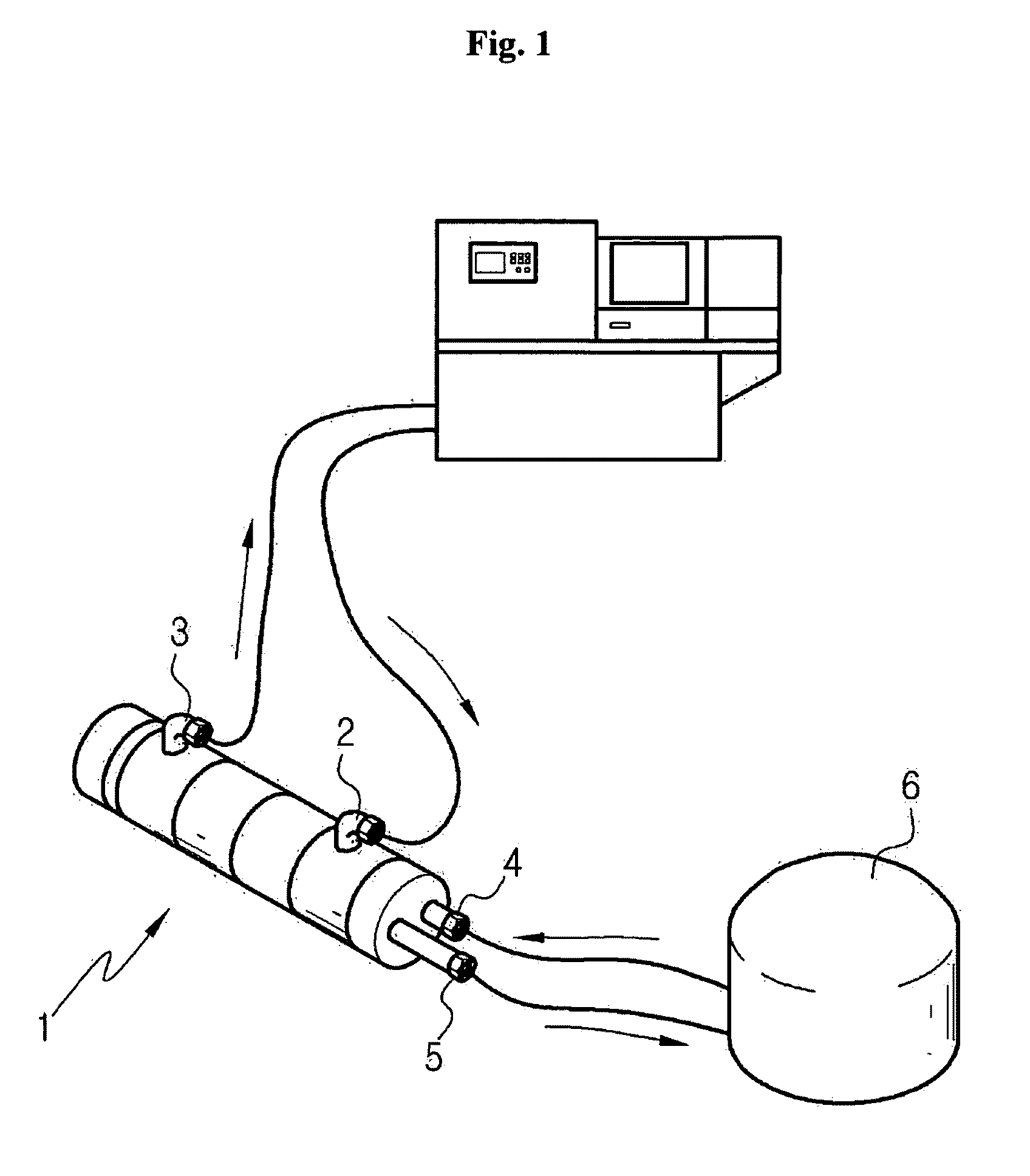
[0021]In the drawings, FIG. 1 is a view showing a use state of the present invention.

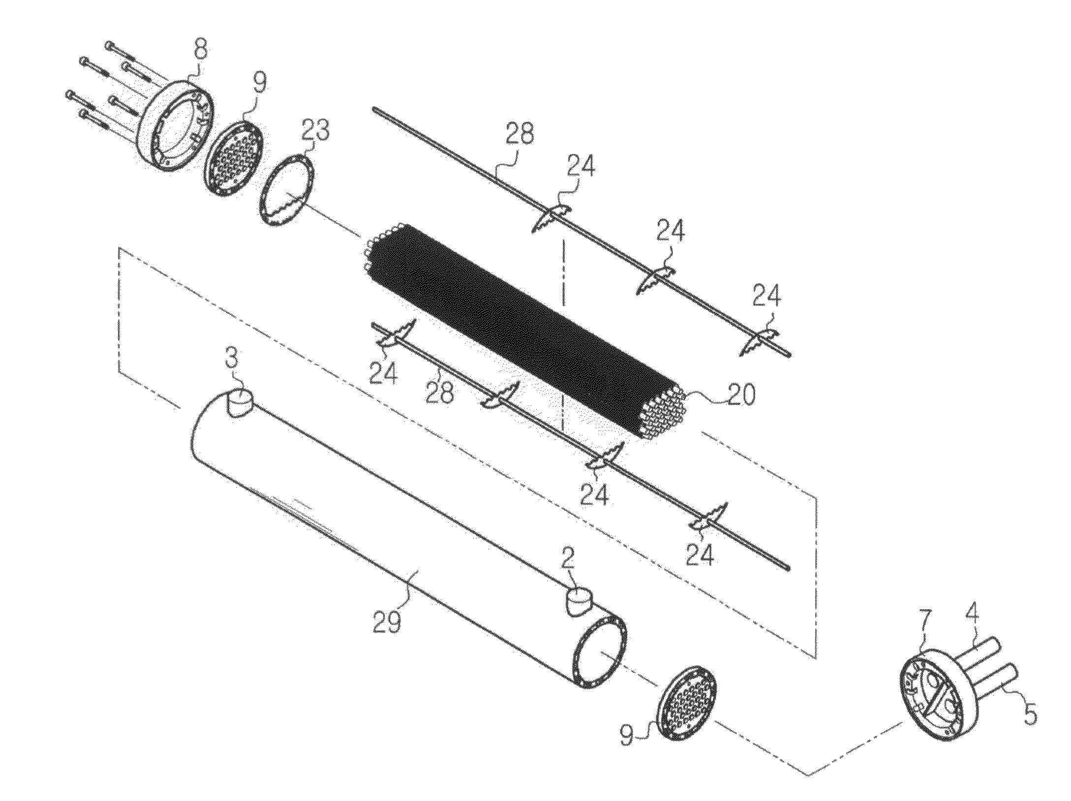
[0022]As shown in FIG. 1, a cooling water inlet 4 and a cooling water outlet 5 of a hydraulic-operating oil cooling apparatus 1 is connected to a cooling water tank 6 so that cooling water can circulate through the inside of a heat exchange pipe 20 disposed at the inside of the hydraulic-operating oil cooling apparatus 1, an oil inlet 2 and an oil outlet 3 of the hydraulic-operating oil cooling apparatus 1 are connected to a hydraulic machine so that hot hydraulic-operating oil can flow through the outer side of the heat exchange pipe 20 disposed at the inside of the hydraulic-operating oil cooling apparatus 1.

[0023]In this regard, heat exchange is produced between the hot hydraulic-operating oil, which is circulating from the hydraulic machine to the hydraulic-op...


PUM


Abstract

An assembly type oil cooler has developed for intensively cooling the various kinds of hydraulic machineries. The oil cooler comprises a main body assembled with a plurality of the body units having a plurality of bolt-holes for assembling and water passages disposed circumferentially for cooling, a plurality of annular-sealing having arched sectors, an oil inlet and an oil outlet are installed at the front and rear of the body units, a pair of front and rear flange plates installed at both end-sides of the body units, a plurality of heat exchange pipes and supporting rods inserted to supporting rod engaging holes through supporting rod holes, a front flange-cap having two compartments to connect a cooling water inlet and an outlet and the body cooling water inlets, and a rear flange-cap having the body cooling water inlets arranged around the body unit for connecting the water passages of the rear flange plate.

Description

TECHNICAL FIELD[0001]The present invention relates to a hydraulic-operating oil cooling apparatus for cooling hydraulic-operating oil used in various hydraulic machines using hydraulic pressure, and more particularly, to an assembly type hydraulic-operating oil cooling apparatus for a hydraulic machine, which is very convenient in maintenance and repair because a body of the oil cooling apparatus is constructed of several units, and is very excellent in cooling efficiency because cooling water flows through the inside of a heat exchange pipe of the hydraulic-operating oil cooling apparatus as well as the inside of the units.BACKGROUND ART[0002]In general, hydraulic machinery such as an injection molding apparatus or a press machine is provided with a cylinder for converting pressure energy into kinetic energy by using hydraulic-operating oil. When the cylinder is operated, heat is generated to thereby increase the temperature of the hydraulic-operating oil. As a result, there occur ...

Claims


Application Information

Patent Timeline
IPC IPC(8): F28D15/00F28F1/10
CPCF28D1/06F28D7/1661F28D2021/0049F28F9/00F28F2009/226F28F9/06F28F9/22F28F2215/00F28F9/0229F15B21/04F28D7/10
Inventor SEO, DONG SOONGCHOI, WAN SOO
Owner SEO DONG SOONG
Why Eureka
Try Eureka