
Endoprosthesis

Active Publication Date: 2010-05-13
BIOTRONIK
View PDF3 Cites 24 Cited by
  • Summary
  • Abstract
  • Description
  • Claims
  • Application Information

AI Technical Summary

Benefits of technology

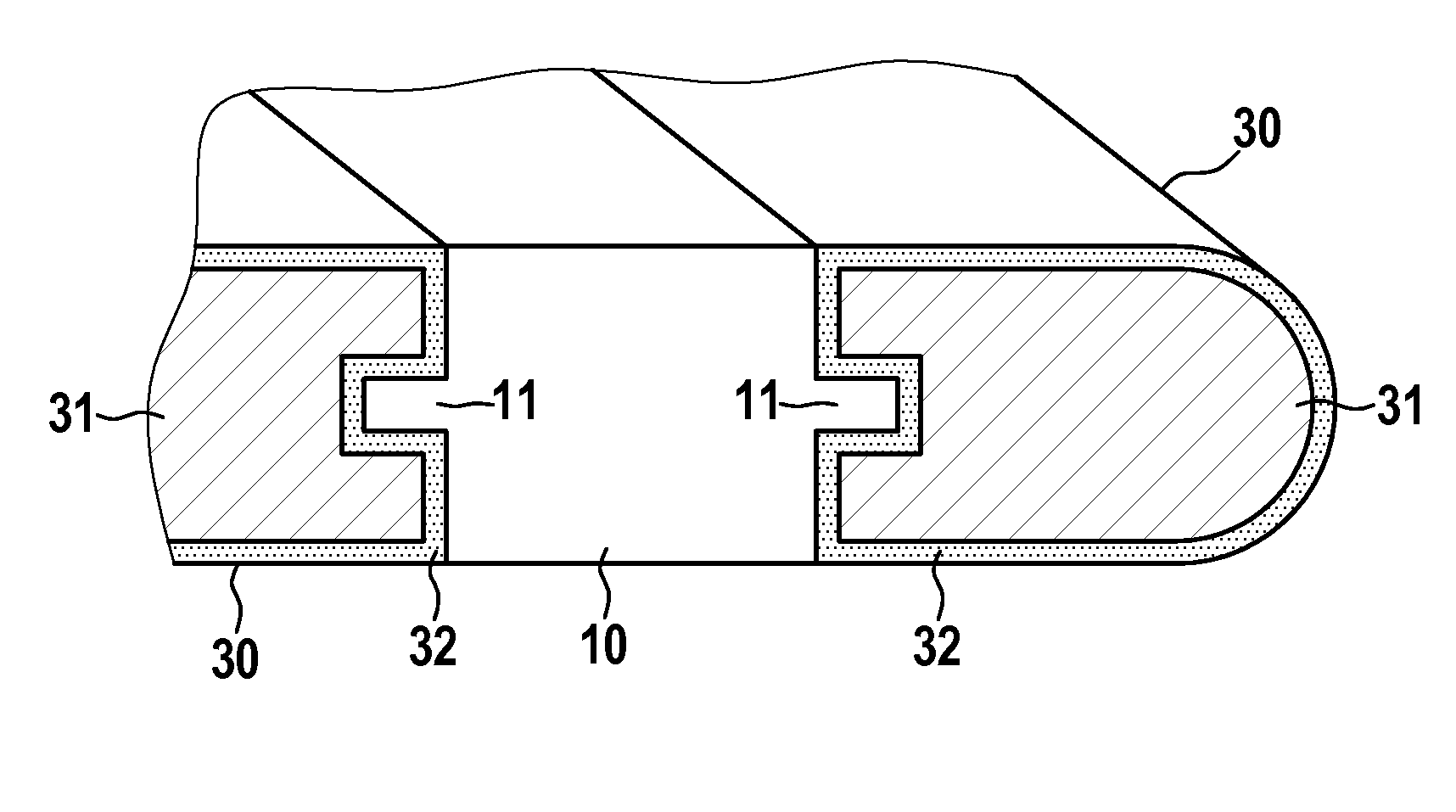
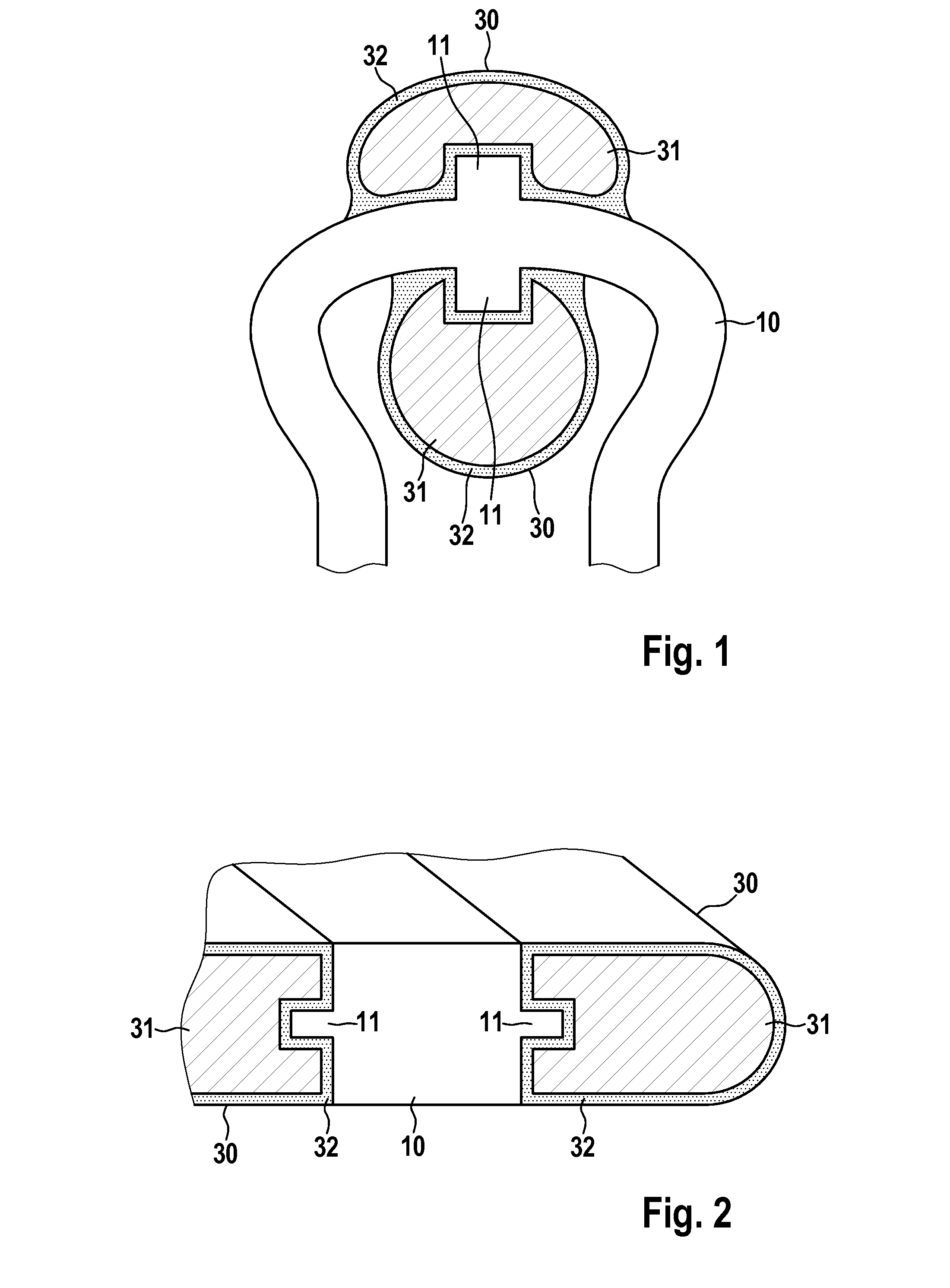
[0016]Such an endoprosthesis according to the invention has the advantage that it does not exhibit a battery effect despite combination of various metals, and therefore has no contact corrosion or, for degradable materials, no unwanted degradation (or acceleration of degradation) of the stent. As a result of the barrier layer the functional element, which represents a radiopaque marker, remains for a longer period of time, and may remain permanently in the treated vessel, so that at a later time the functional element still indicates the implantation site of the endoprosthesis, for example even when the endoprosthesis is already partially degraded.
[0024]It is particularly easy to affix functional elements to the base body when the functional elements have at least one through opening for attachment to the base body. Alternatively or additionally, the functional elements may provide [sic; be provided with] a circumferential groove for attachment to the base body.
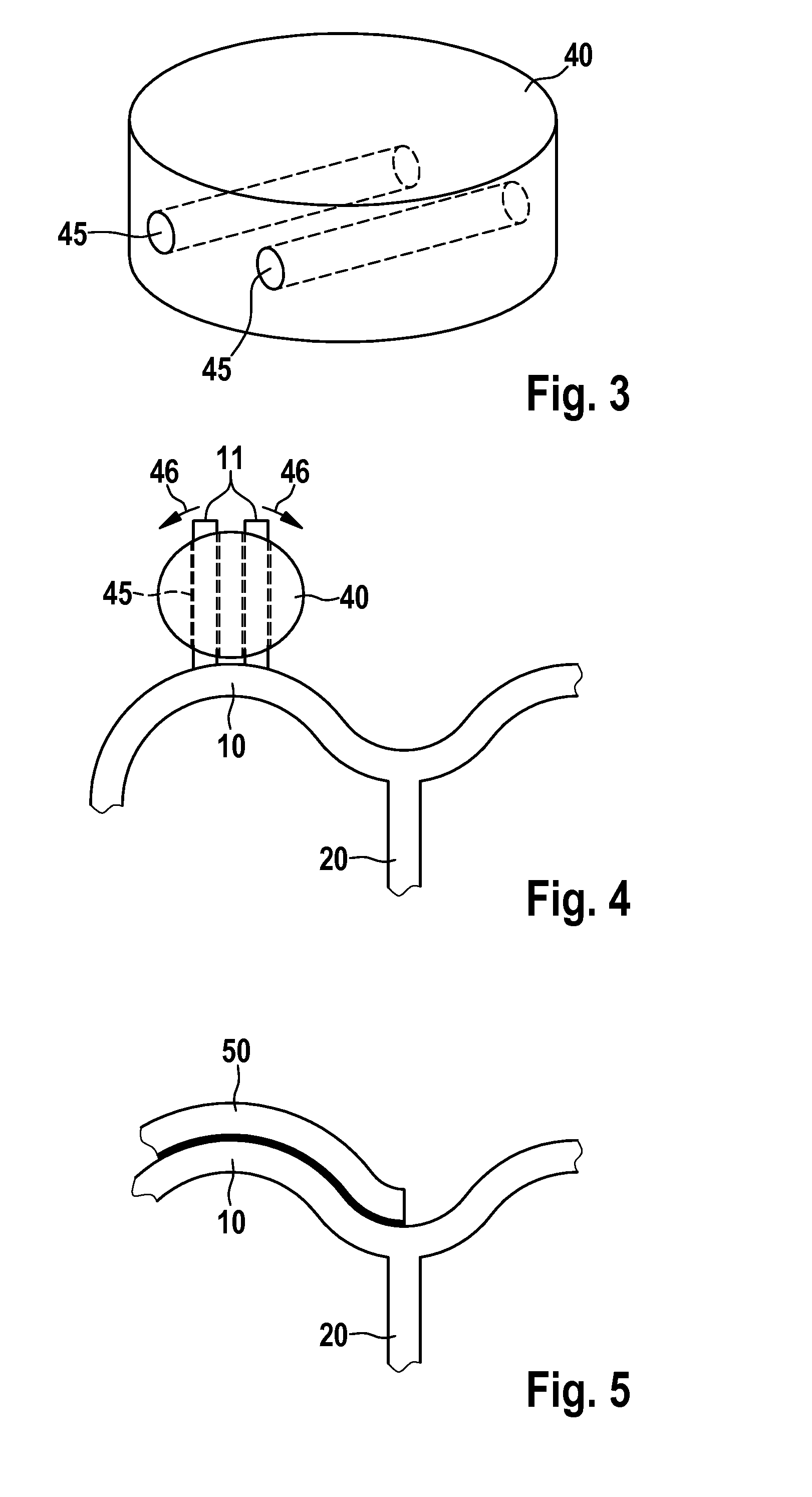
[0025]The functional elements may likewise be easily affixed to the base body when the functional element together with the barrier layer has a wire-shaped design. In this case, such functional elements are preferably affixed parallel to a structure of the base body.
[0026]Furthermore, it is advantageous for the geometry of the functional element and / or the connection of the functional element to the base body to be selected in such a way that the activity of the endoprosthesis, preferably the stent, is not greatly impaired with regard to the clinical supporting effect after crimping, tracking, or dilation. Likewise, the aim is to facilitate complete growth into the treated vessel (neointima formation). In this regard the flow of bodily fluid must not be hindered. Therefore, in one preferred exemplary embodiment the functional element is not allowed to project into the stent lumen. For this purpose the functional element should have a non-circular or non-oval full cross section in at least one direction, thus preventing complete blockage of a vessel. Polygonal functional elements or functional elements with pronounced through holes, for example, are suitable. If possible, the functional elements are also situated at the end position, i.e., at one or both ends in the longitudinal direction of the endoprosthesis, since in this case the end points of the endoprosthesis may be easily identified in the X-ray image.

Problems solved by technology

Such a distribution of radiopaque particles generally does not provide for sufficient density of these materials, and therefore the radiopacity is too low for many applications.
For stents having a base body composed of a metallic material, when functional elements, for example radiopaque elements made of gold or silver, are provided on the base body of the stent the problem of contact corrosion occurs at the contact region between the material of the base body and the material of the functional element.
This results in destruction of the stent, or separation of the functional element from the stent structure, so that the endoprosthesis can no longer perform its function, or may not be able to be found.
The above-described endoprostheses from the prior art provide no solution to this problem.

Method used


Image

  • Endoprosthesis
  • Endoprosthesis
  • Endoprosthesis

Examples


Embodiment Construction

[0035]FIG. 1 shows a section of a base body designed as a lattice in a first exemplary embodiment of an endoprosthesis according to the invention embodied as a stent. The base body has webs folded in a zigzag or meandering manner and extending essentially in the circumferential direction or helically as support elements 10, and has webs extending essentially in the longitudinal direction of the stent as connecting elements 20 (see FIG. 4). The section illustrated in FIG. 1 is part of a support element 10. As a whole, the stent is designed as a tubular or hollow cylindrical endoprosthesis which is open at the ends and extends in the direction of the connecting webs 20.

[0036]In the region of an essentially circular section, the support element 10 has finger-shaped sections 11 which extend in the longitudinal direction of the stent. At each finger-shaped section 11 a functional element 30 is provided which has a core 31 composed of radiopaque (X-ray opaque) material such as platinum, i...


PUM

PropertyMeasurementUnit
Lengthaaaaaaaaaa
Lengthaaaaaaaaaa
Lengthaaaaaaaaaa

Abstract

The invention relates to an endoprosthesis, in particular an intraluminal endoprosthesis, for example a stent, having a base body composed at least partially of a metallic material, and having a functional element which is attached to the base body or imbedded therein and which contains material that is radiopaque and / or X-ray opaque and has a different material composition, at least in a portion of its volume, compared to the material of the base body. To avoid contact corrosion and undesired corrosion, the functional element is provided with a barrier layer which electrically insulates the radiopaque and / or X-ray opaque material from the base body.

Description

CROSS REFERENCE TO RELATED APPLICATIONS[0001]This invention claims benefit of priority to Germany patent application serial number DE 10 2008 043 642.9, filed on Nov. 11, 2008; the contents of which are herein incorporated by reference in their entirety.FIELD OF THE INVENTION[0002]The present invention relates to an endoprosthesis or implant, in particular an intraluminal endoprosthesis. for example a stent, having a base body composed at least partially of a metallic material, and having a functional element which is attached to the base body or imbedded therein.BACKGROUND OF THE INVENTION[0003]Stents are endovascular prostheses which may be used for the treatment of stenoses (vascular constrictions). Stents have a base body in the form of a hollow cylindrical or tubular base lattice which is open at both longitudinal ends of the tube. The tubular base lattice of such an endoprosthesis is inserted into the vessel to be treated, and is used to support the vessel.[0004]Such stents or...

Claims


Application Information

Patent Timeline
IPC IPC(8): A61F2/82A61F2/86A61F2/91
CPCA61F2/86A61F2/91A61F2210/0004A61F2220/005A61L31/10A61L31/18A61F2250/0098
Inventor KLOCKE, BJOERNRIEDMUELLER, JOHANNES
Owner BIOTRONIK
Learn More