Eureka AIR delivers breakthrough ideas for toughest innovation challenges, trusted by R&D personnel around the world.

Modular LED flood light

a flood light and modular technology, applied in the field of illumination, can solve the problems of economic cost, long life, relatively uncomplicated construction, etc., and achieve the effect of convenient cutting and easy adjustmen

Active Publication Date: 2010-05-13
LOMAK IND COMPANY LIMITED
View PDF4 Cites 55 Cited by
  • Summary
  • Abstract
  • Description
  • Claims
  • Application Information

AI Technical Summary

Benefits of technology

[0008]The present invention addresses the above stated need by providing a design for luminaires which utilize LEDs which lends itself to producing many different output configurations and capacities while using a common core of components for construction of such luminaires. In one aspect, the present invention contemplates a modular design for LED using luminaires which is readily adjustable as to light source layout in two orthogonal directions. In another aspect of the invention, a luminaire may be assembled from a minimum number of component parts. According to a further aspect of the invention, a significant LED bearing component may be fabricated as an extrusion of indefinite length, which is readily cut to a desired length.
[0012]One of the end pieces accommodates an integral clamp, which allows the luminaire to be mounted to a pole. The clamp accommodates many different dimensions and configurations of poles, so that the novel luminaire need not require careful coordination with any one design or model of pole.
[0013]The end pieces are somewhat arcuate, so that the pattern of LEDs mounted thereto is that of a curved plane. This both allows for advantageous projection of light in overlapping beams, and also provides an inherent glare suppression feature for protecting observers at a distance from the luminaire. Overlapping beams of light assure illumination coverage even in the event that one or several LEDs fail.
[0014]Electrical components serving the individual LEDs may be mounted to the luminaire in a way that avoids interfering with heat dissipation through the heat sinks.
[0015]It is therefore an object of the invention to provide a design for a luminaire which utilizes LEDs which is both modular and also readily adjustable as to dimensions of the array of individual LEDs.
[0016]It is an object of the invention to provide improved elements and arrangements thereof by apparatus for the purposes described which is inexpensive, dependable, and fully effective in accomplishing its intended purposes.

Problems solved by technology

LEDs enjoy not only relatively high efficiency, but offer long life and relatively uncomplicated construction.
While this situation offers great versatility in providing varieties of luminaires, such convenience comes at economic cost.

Method used


Image

  • Modular LED flood light
  • Modular LED flood light
  • Modular LED flood light

Examples


Embodiment Construction

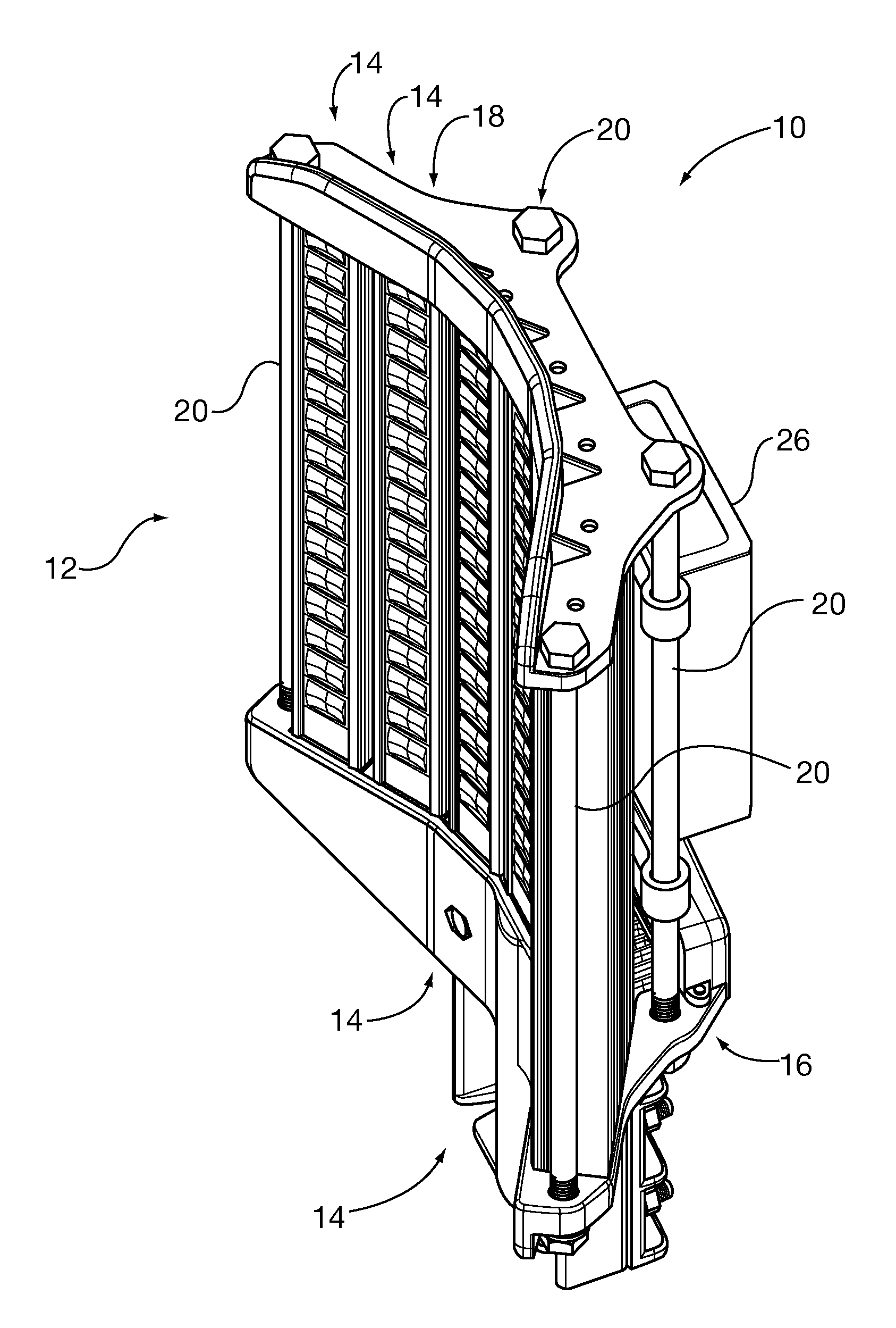
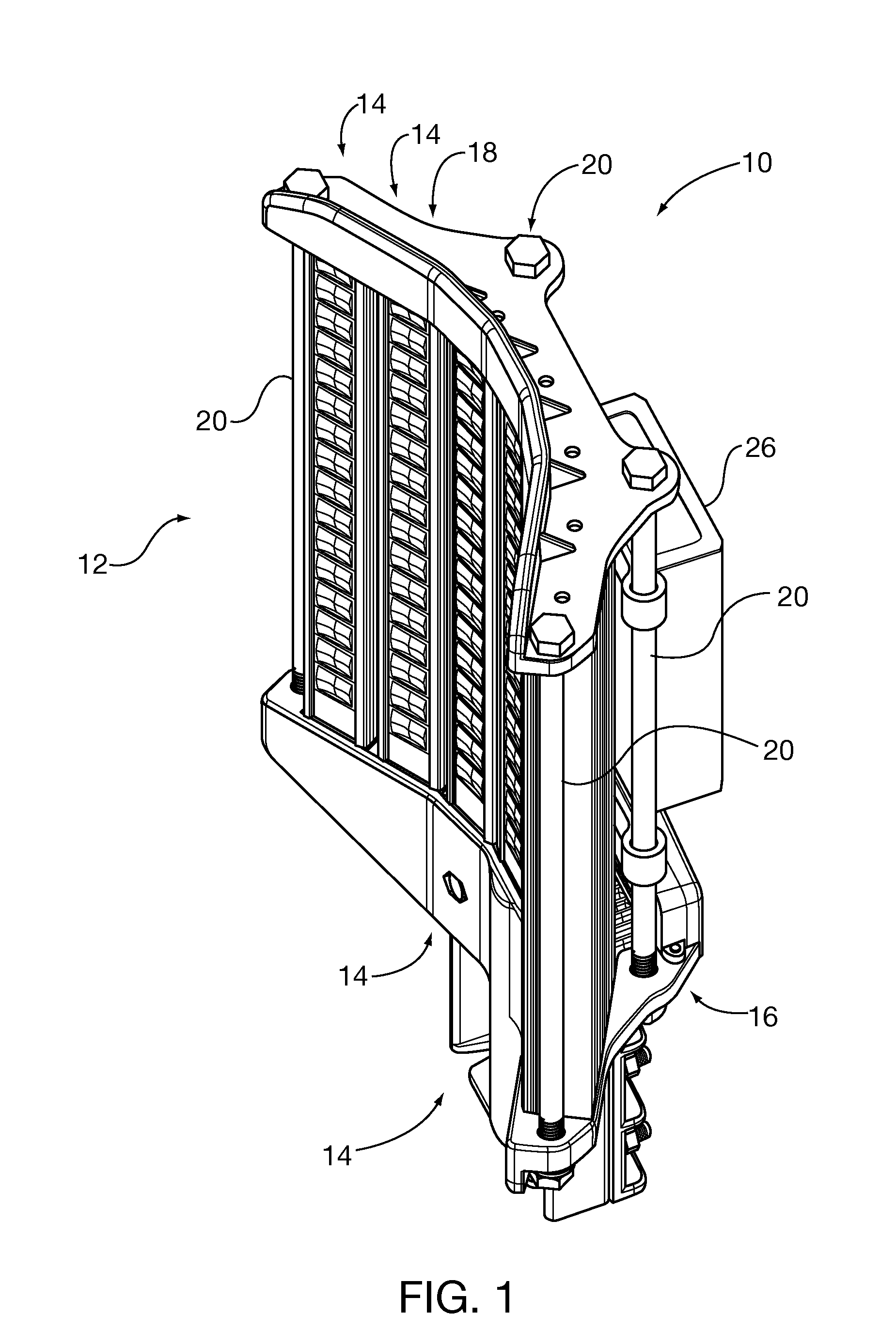
[0031]FIG. 1 of the drawings shows a modular luminaire 10 according to at least one aspect of the invention. The modular luminaire 10 is of a type which may be used as a street light, for example. The modular luminaire 10 may comprise a plurality of LEDs 12 (not all of which are individually called out by reference numeral) arranged along and ultimately supported by heat sinks 14 (see FIG. 2). The heat sinks 14 are suspended between a proximal end piece 16 and a distal end piece 18, which are in turn compressed towards one another and against the heat sinks 14 by through bolts 20. The through bolts 20 extend from the proximal end piece 16 to the distal end piece 18 and unite the proximal end piece 16 and the distal end piece 18, while drawing the proximal end piece 16 towards the distal end piece 18 while entrapping each one of the heat sinks 14 between the proximal end piece 16 and the distal end piece 18.

[0032]The component parts of the modular luminaire 10 are better seen in the ...


PUM


Abstract

A modular luminaire which uses LED light sources. The basic frame comprises two end pieces compressed together by through bolts. At least one elongated heat sink is compressed between the end pieces. Each heat sink may bear a plurality of LEDs mounted on a printed circuit board which may have an integral metallic backplate, and is installed on one of the heat sinks with a layer of heat conductive grease therebetween. The heat sinks have fins projecting in three directions, the fourth direction being accounted for by the LEDs, and are rotatable about their longitudinal axes to adjust direction of light propagation. The heat sinks are arrayed in an arc, so that the outside heat sinks shield observers from direct glare from opposed heat sinks. Heat sinks may be extruded to form cooling fins and slots which may receive fasteners such as screws.

Description

CROSS-REFERENCE TO RELATED APPLICATIONS[0001]This application claims the benefit of the filing date under 35 USC 119(a) of Chinese Patent Application No. 200820203225.7, filed Nov. 11, 2008, the contents of which are incorporated herein by reference. This application is also related to HEAT SINK FOR MODULAR LED FLOOD LIGHT and LENS FOR LIGHT EMITTING DIODES MOUNTED ON A HEAT SINKT, both of common ownership with the present invention, and filed of even date herewith.FIELD OF THE INVENTION[0002]The present invention relates to illumination, and more particularly to a flood light having modular construction.BACKGROUND OF THE INVENTION[0003]Lights for illuminating large areas such as roads, parking lots, fields, and the like have long been provided. Lighting technology for such lights has progressed from incandescent to specialized high powered types such as sodium vapor and mercury vapor. However, it has become desirable to utilize more efficient light sources, as efficiency relates to...

Claims


Application Information

Patent Timeline
Patent Type & Authority Applications(United States)
IPC IPC(8): F21V21/00
CPCF21S2/005F21Y2113/00F21S48/328F21V15/013F21V15/015F21V19/001F21V19/02F21V21/116F21V29/004F21W2131/103F21W2131/105F21Y2101/02F21Y2103/003F21V31/005F21S9/03F21V29/745F21V29/75F21V29/763F21V29/767Y02B20/72F21S8/088F21Y2103/10F21Y2115/10F21V29/74F21V29/71F21S45/47
Inventor LO, CHI WAI
Owner LOMAK IND COMPANY LIMITED
Why Eureka
Eureka Blog
Learn More