Liquid crystal device and method of driving the same

a liquid crystal device and liquid crystal technology, applied in the direction of instruments, computing, electric digital data processing, etc., can solve the problems of deteriorating display performance, reducing contrast ratio, and system not fully using the advantage of high aperture ratio, etc., to achieve the effect of suppressing performance deterioration

Inactive Publication Date: 2010-05-13
NANO LOA
View PDF8 Cites 10 Cited by
  • Summary
  • Abstract
  • Description
  • Claims
  • Application Information

AI Technical Summary

Benefits of technology

[0011]Another object of the present invention is to provide a liquid crystal device capable of effectively suppressing a reduction in contrast (especially, a reduction in contrast at a low gray shade).
[0013]As a result of further study, the present inventors have also found that it is very effective in attaining the above-mentioned object to apply a reverse electric field (i.e., s-application of electric field: −TINT) so as to cancel an orientation energy difference (TINT) depending upon relative directions between the applied electric field and aligned liquid crystal molecular axis in the liquid crystal element.
[0028]Also, as illustrated in the graph of FIG. 6, TN-LCD has a threshold value of the Freedericksz transition of about 1 V and therefore, the delay in optical response particularly at a low voltage raises substantially no problem.
[0030]The technology of polarization shielded smectic liquid crystal display (hereinafter simply referred to as “PSS-LCD”; for details of this PSS-LCD, for example, Kohyo (National Publication of Translated Version) No. 2006-515935 may be referred to) previously proposed by the present inventors is a technique where a liquid crystal element not having the above-described spontaneous polarization can be obtained and this liquid crystal element can show an electro-optical response at about 150 microseconds and can continuously display a gray shade scale according to the applied voltage. In the PSS-LCD, “applying a reverse electric field” according to the present invention may be particularly effective (for example, from the standpoint of suppressing the performance deterioration due to a slight delay in optical response speed in the case of low gray shade).

Problems solved by technology

However, this system could not fully use the advantage of high aperture ratio due to the nature of TN optical response profile as illustrated in FIG. 25.
In addition, due to light leakage at “black” level, a significant reduction in the contrast ratio tends to occur at the same time with color mixing, which may incur deterioration of the display performance.

Method used


Image

  • Liquid crystal device and method of driving the same
  • Liquid crystal device and method of driving the same
  • Liquid crystal device and method of driving the same

Examples


embodiment 1

(Usable PSS-LCD; Another Embodiment 1)

[0144]According to another embodiment, there is provided: a liquid crystal device comprising: at least, a pair of substrates; a liquid crystal material disposed between the pair of substrates; and a pair of polarizing films disposed on the outside of the pair of substrates; wherein one of the pair of polarizing films has a molecular initial alignment which is parallel or almost parallel with the alignment treatment direction for the liquid crystal material; the other of the pair of polarizing films has a polarizing absorption direction which is perpendicular to the alignment treatment direction for the liquid crystal material; and, the liquid crystal device shows an extinction angle under the absence of an externally applied voltage.

[0145]The liquid crystal display according to such an embodiment has an advantage that the extinction position thereof does not substantially have a temperature dependency, in addition to those as described above.

[01...

embodiment 2

(Usable PSS-LCD; Another Embodiment 2)

[0150]According to a further embodiment, there is provided: a liquid crystal device comprising: at least, a pair of substrates; and a liquid crystal material disposed between the pair of substrates; wherein the current passing through the pair of substrates shows substantially no peak-shaped current, when a continuously and linearly changing voltage waveform is applied to the liquid crystal device.

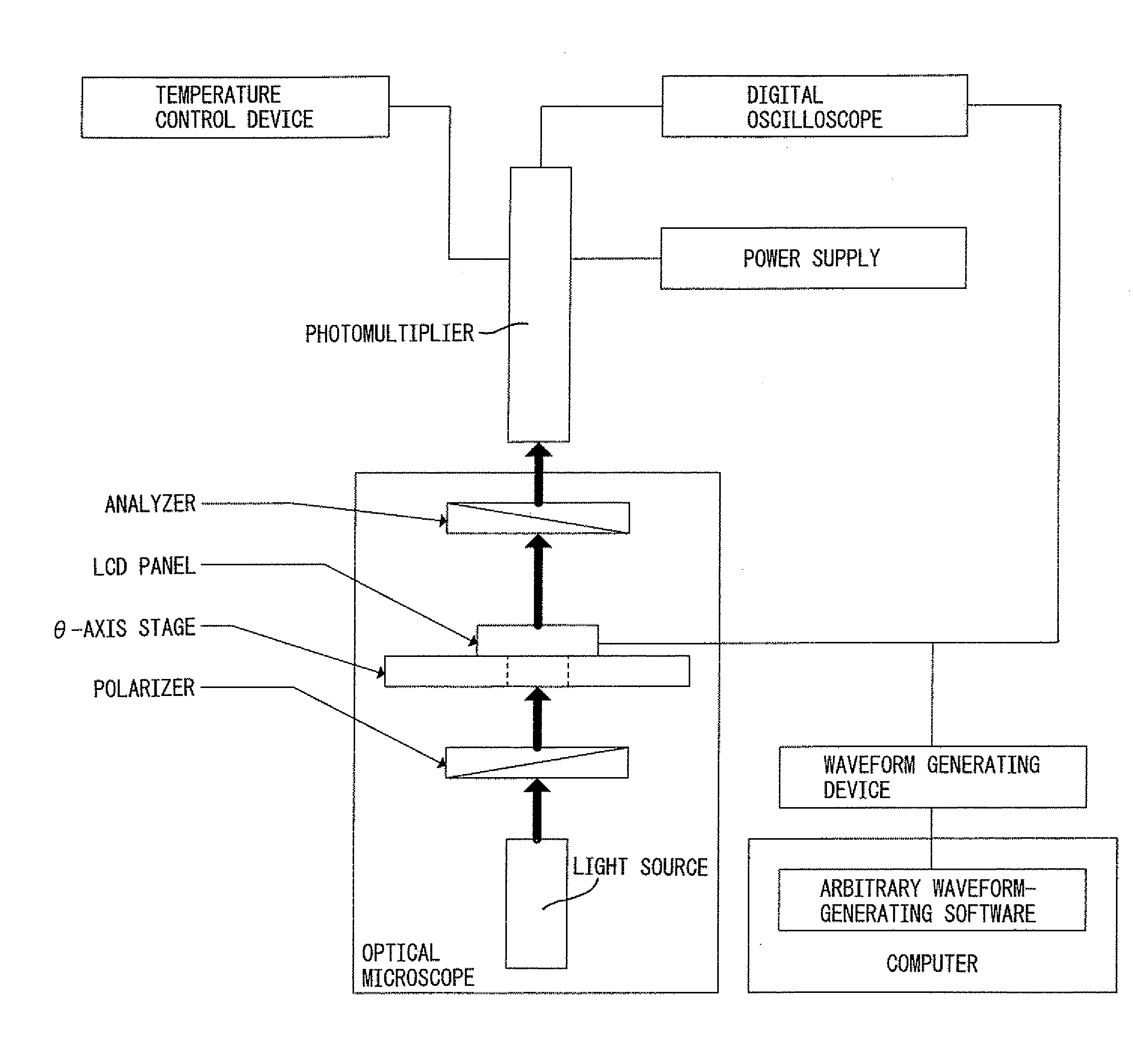
[0151]The current passing through the pair of substrates does not substantially show a peak-shaped current, under the application of a voltage waveform of which strength is continuously and linearly changed, may be confirmed, e.g., by the following method. In this embodiment, “the current does not substantially show a peak-shaped current “means that, in the liquid crystal molecule alignment change, the spontaneous polarization does not participate in the liquid crystal molecule alignment change, at least in a direct manner. The liquid crystal display a...

embodiment 3

(Usable PSS-LCD; Another Embodiment 3)

[0155]According to a further embodiment of the present invention, there is provided: a liquid crystal device wherein the liquid crystal molecular alignment treatment for the liquid crystal material is conducted in conjunction with a liquid crystal molecular alignment material providing a low surface pre-tilt angle.

[0156]In this embodiment, the pre-tilt angle may preferably be 1.5 degrees or less, more preferably 1.0 degree or less (particularly 0.5 degree or less). The liquid crystal display according to such an embodiment has an advantage, in addition to those describe above, that it can provide uniform alignment in a wide area, and a wide view angle.

[0157]The reason why the wide view angle is provided is as follows.

[0158]In the liquid crystal molecule alignment according to the present invention, liquid crystal molecules may be moved within cone-like regions, and the electro-optical response thereof does not remain in the same plane. Generally...


PUM


Abstract

A liquid crystal device comprising, at least, a liquid crystal element comprising at least a pair of substrates and a liquid crystal material disposed between the pair of electrodes, and electric field-applying means for applying an electric field to the liquid crystal element. The electric field-applying means applies a reverse electric field (−TINT) so as to cancel an orientation energy difference (TINT) depending upon relative directions between the applied electric field and aligned liquid crystal molecular axis in the liquid crystal element. There is provided a liquid crystal device capable of effectively suppressing the reduction in contrast, even when the optical response speed is increased.

Description

TECHNICAL FIELD[0001]The present invention relates to a liquid crystal device capable of realizing an excellent optical response speed and an excellent display performance. More specifically, the present invention relates to a liquid crystal device capable of realizing an excellent optical response speed and capable of solving a slight delay in the optical response speed, especially delay in the case of low gray shade (or low gray scale).[0002]In recent years, combined with the progress in technology aiming at a so-called “ubiquitous society”, various needs for the display technique in general, such as high-speed response, downsizing and high display quality, are sophisticated. In order to meet these needs, also in the field of a liquid crystal device having advantage of ubiquitous application in view of downsizing and power saving, the demand for a liquid crystal device capable of realizing an excellent optical response speed and an excellent display performance is more and more in...

Claims


Application Information

Patent Timeline
IPC IPC(8): G09G3/36G02F1/133G09G5/00
CPCG09G3/3614G09G3/3629G09G2310/0235G09G2360/145G09G2320/066G09G2320/0693G09G2320/0252G02F1/133G09G3/36
Inventor HORI, TETSURO
Owner NANO LOA
Why Eureka
Try Eureka