
Energy storage device and method of use

a technology of energy storage and discharge device, which is applied in the direction of dynamo-electric machines, motors, couplings, etc., can solve the problems of low-loss flywheels that rotate at very high speeds, relatively new and undeveloped, and achieve the effects of minimizing friction, minimizing energy loss of the system, and minimizing friction

Inactive Publication Date: 2010-05-13
KWOK JAMES
View PDF10 Cites 44 Cited by
  • Summary
  • Abstract
  • Description
  • Claims
  • Application Information

AI Technical Summary

Benefits of technology

[0025]The present invention is directed to an energy storage device, which may at least partially overcome at least one of the abovementioned disadvantages or provide the consumer with a useful or commercial choice.

Problems solved by technology

Prior art FES systems have been used mainly for automotive and space applications and have yet to become accepted due to their complexity, low net power output and fragility in operating conditions.
For example, for automotive applications, dynamic isolation problems are present.
Though the concept of flywheels is not new, low-loss flywheels that rotate at very high speeds are relatively new and undeveloped.
There are a variety of problems present in adapting the conventional centrifugal clutch to use in flywheel energy storage systems as will become apparent from the following discussion.

Method used


Image

  • Energy storage device and method of use
  • Energy storage device and method of use
  • Energy storage device and method of use

Examples


Embodiment Construction

[0132]According to a particularly preferred embodiment, an energy storage device is provided.

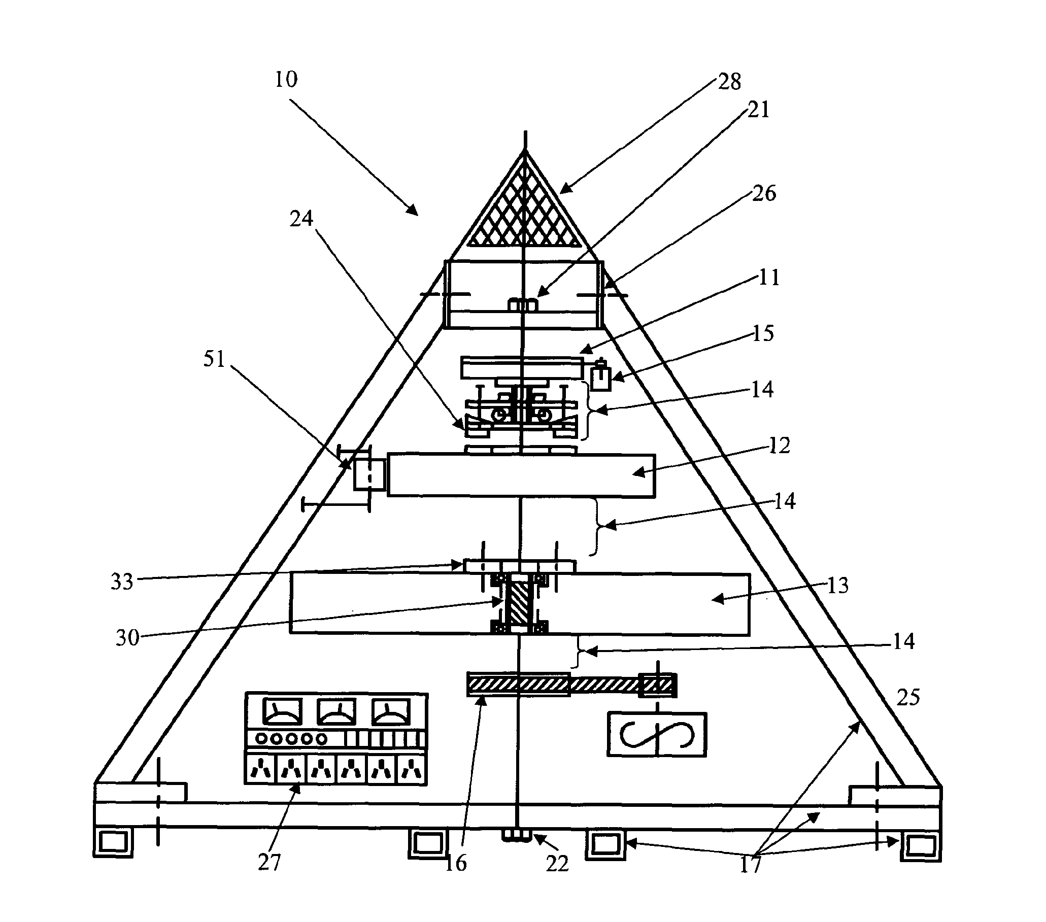
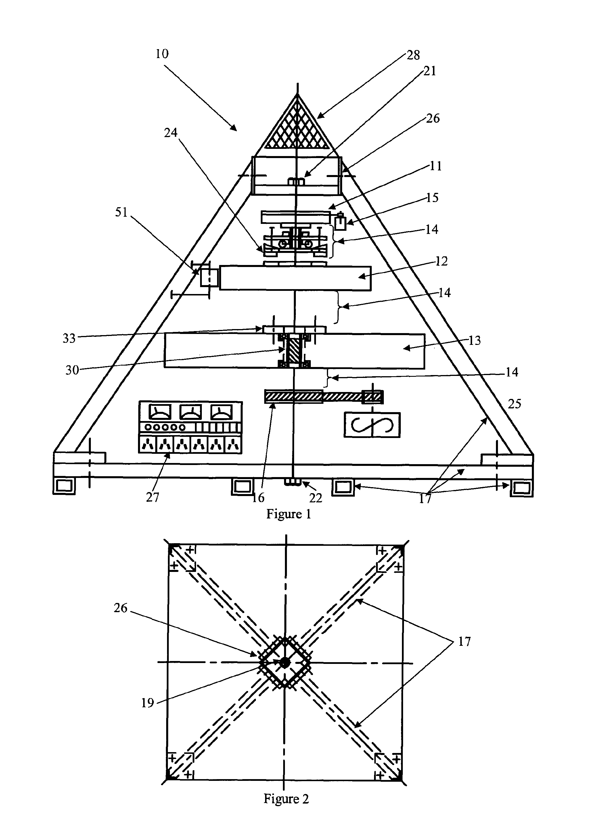
[0133]The energy storage device 10 of the embodiment illustrated in FIGS. 1 and 2 in particular includes a shaft member (not shown in FIG. 1) with a multistage flywheel system. According to the embodiment in FIG. 1, there are three flywheels including a first flywheel 11, a second flywheel 12 larger than the first flywheel 11, and a third flywheel 13 larger than the second flywheel 12. Each flywheel is mounted for rotation about the shaft member.

[0134]There is a clutch assembly 14 located between each of the flywheels and a low power input motor 15 and a power take-off wheel 16 associated with the third flywheel 13.

[0135]The first flywheel 11 is rotated using the low power input motor 15 and is accelerated to a predetermined rotational velocity whereupon the clutch assembly 14 engages to connect the first 11 and second 12 flywheels allowing inertial and kinetic energy to transfer between the...


PUM


Abstract

An energy storage device including at least one shaft member, at least a pair of flywheels including a first flywheel and a second flywheel larger than the first flywheel, each flywheel associated with the at least one shaft member, a clutch assembly associated with each of the flywheels, at least one low power input device, and a power take off means associated with the second flywheel, wherein the first flywheel is rotated using a low power input device and is accelerated to a predetermined rotational velocity whereupon the clutch assembly engages to connect the first and second flywheels allowing inertial and kinetic energy to transfer between the flywheels to accelerate the second flywheel.

Description

FIELD OF THE INVENTION[0001]The present invention relates to energy storage and discharge devices and particularly to those of a type known as flywheel energy storage devices.BACKGROUND ART[0002]A report published in February 1997 by Sandia National Laboratories entitled “Cost Analysis of Energy Storage Systems for Electric Utility Applications” contains a summary of the developments and the potential that energy storage systems of differing types have. Excerpts from that report are as follows:[0003]“Energy Storage (ES) systems could potentially have widespread applications within the electric utility industry. Three promising storage technologies—Battery Energy Storage (BES), Superconducting Magnetic Energy Storage (SMES) and Advanced Flywheel Energy Storage (FES)—each meet some of the performance requirements of the 13 utility applications identified in the Battery Energy Storage for Utility Applications: Phase I—Opportunities Analysis study conducted by Sandia National Laboratori...

Claims


Application Information

Patent Timeline
IPC IPC(8): F03G3/08H02K7/02
CPCF03G3/08F16D43/10Y10T74/2117Y02E60/16H02K7/025
Inventor KWOK, JAMES
Owner KWOK JAMES
Learn More