
Cryopump

a technology of cryopump and liquid reservoir, which is applied in the direction of positive displacement liquid engine, separation process, lighting and heating apparatus, etc., can solve the problems of reducing regeneration efficiency and taking a long time to volatilize residual liquid, and achieve short period of time, efficient discharge of other molecules, and short period of time

Inactive Publication Date: 2010-05-13
SUMITOMO HEAVY IND LTD
View PDF9 Cites 7 Cited by
  • Summary
  • Abstract
  • Description
  • Claims
  • Application Information

AI Technical Summary

Benefits of technology

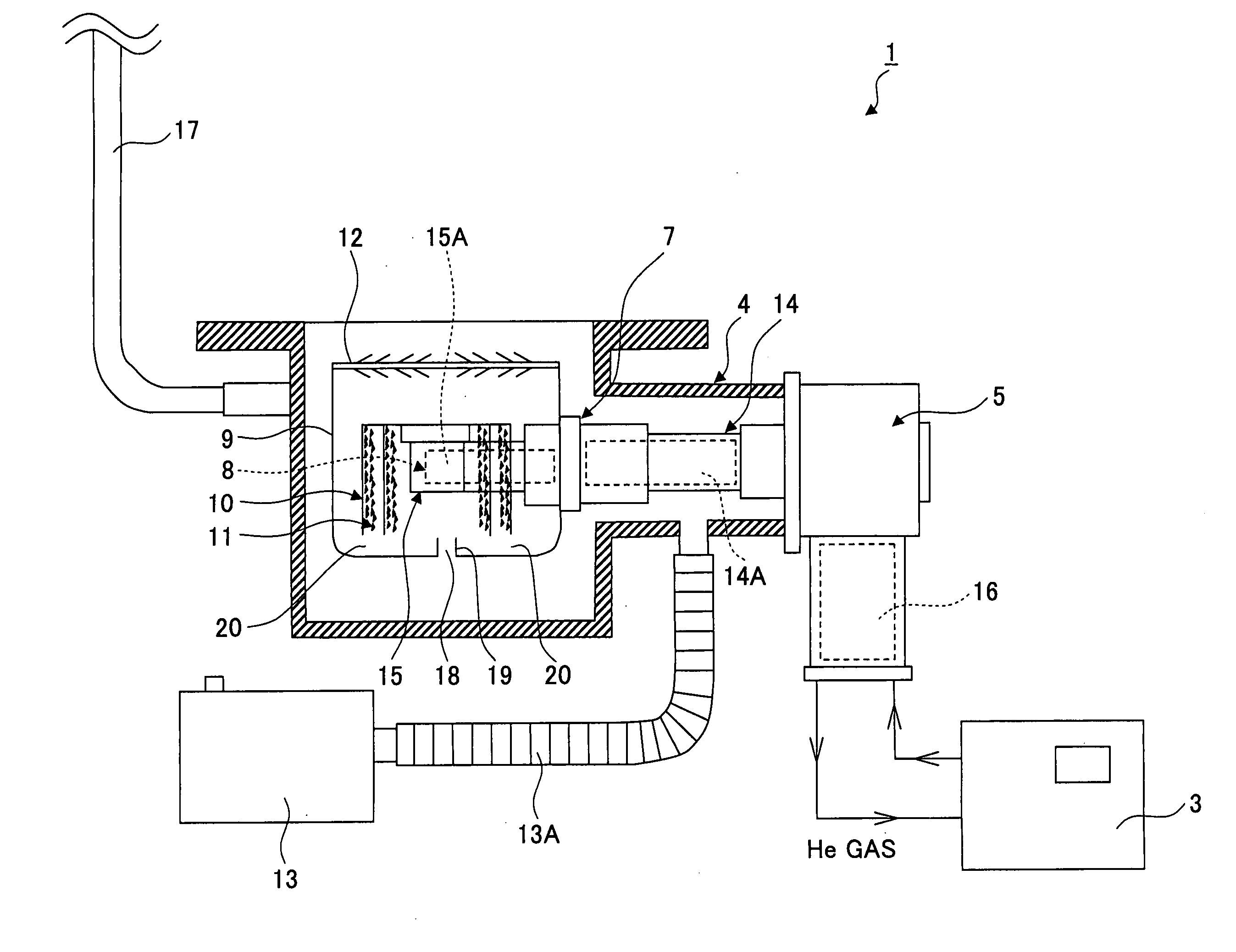
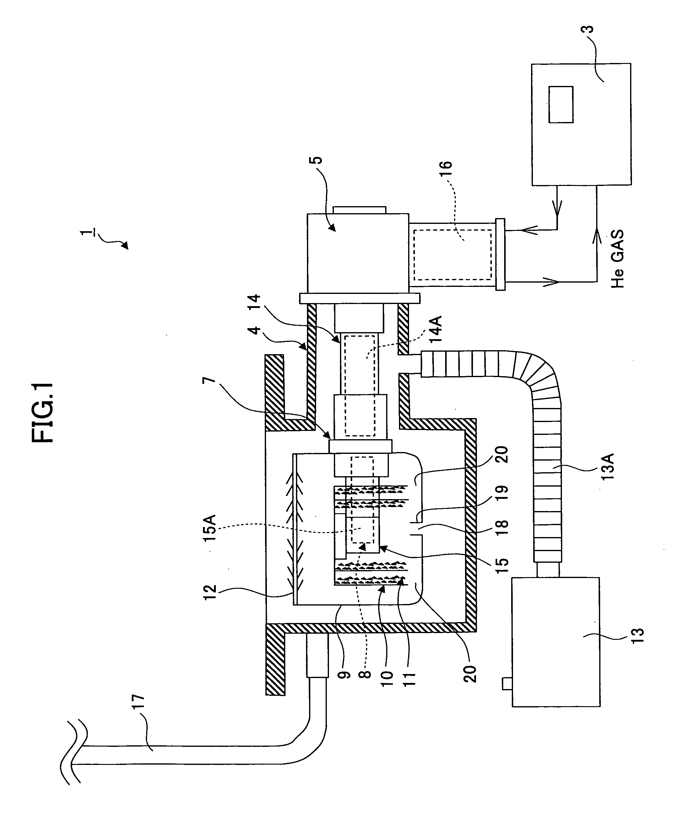
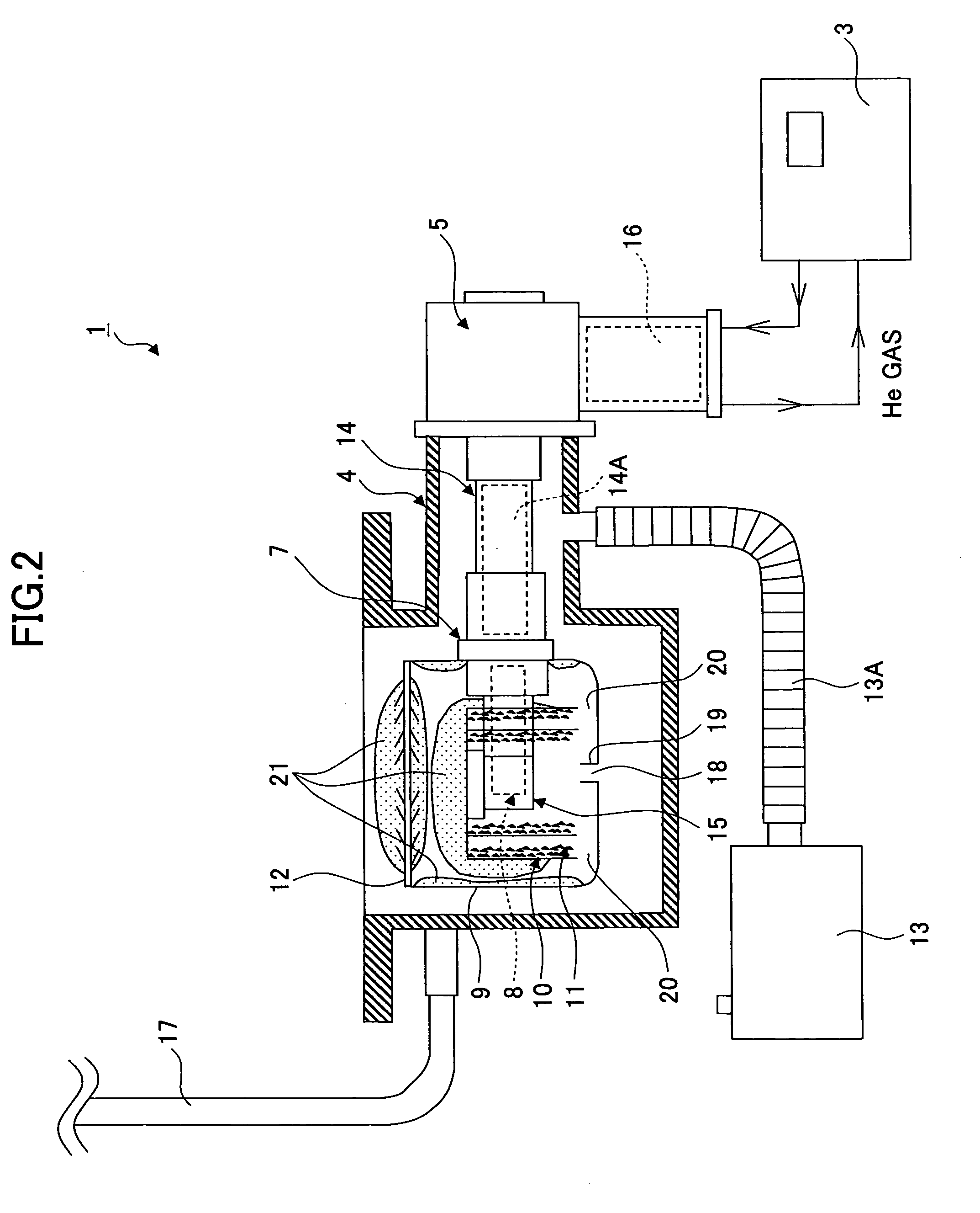
[0016]According to the embodiment of the present invention, the flow-out hole configured to flow out molecules other than liquefied water to the vacuum chamber is provided in the shield. Therefore, the molecules other than liquefied water use heat of the vacuum chamber having a normal temperature and are volatilized so as to be discharged. Therefore, it is possible to efficiently discharge the molecules other than liquefied water from the cryopump in a short period of time.

Problems solved by technology

Accordingly, it takes a long time to volatilize the residual liquid and therefore regeneration efficiency is reduced.

Method used


Image

  • Cryopump
  • Cryopump
  • Cryopump

Examples


Embodiment Construction

[0051]A description is given below of embodiments where a cryopump is applied, with reference to FIG. 1 through FIG. 8 according to embodiments of the present invention.

[0052]FIG. 1 shows a cryopump of the embodiment of the present invention. A cryopump 1 is provided in a process chamber not illustrated in FIG. 1 (for example, a process chamber of a semiconductor manufacturing apparatus). The inside of the process chamber is under vacuum. The cryopump 1 includes a compressor 3, a vacuum chamber 4, a cryogenic cooler 5, a shield 9, a cryopanel 10 and others. Temperatures of the shield 9 and the cryopanel 10 at the time of regeneration are increased based on a so-called reverse temperature increase where the cooling cycle of the cryogenic cooler 5 is reversed.

[0053]The compressor 3 is configured to increase the pressure of coolant gas such as helium gas so as to supply the coolant gas to the cryogenic cooler 5. In addition, the compressor 3 is configured to receive the coolant gas bei...


PUM

PropertyMeasurementUnit
boiling pointaaaaaaaaaa
heightaaaaaaaaaa

Abstract

A cryogenic refrigerator of a cryopump generates cryogenic cooling in an expansion volume by reciprocally moving a displacer in a cylinder. A cryopanel and a cup-shaped shield are received in a vacuum chamber of the cryopump and are cooled by the cryogenic cooling. The shield protects the cryopanel from radiant heat of the vacuum chamber. A louver is provided at an upper opening of the shield. A hole is formed at a bottom or side of the cup-shaped shield defining a storage part. Molecules in the vacuum chamber are solidified at or absorbed by the cryopanel and the shield. During regeneration, temperature of the cryopanel and the shield is increased. Water molecules desorbed and liquefied from the louver, the shield or the cryopanel are accumulated during regeneration at the storage part that has enough volume to store the water molecules.

Description

TECHNICAL FIELD[0001]The present invention generally relates to cryopumps (cryogenic pumps). More specifically, the present invention relates to a cryopump which can achieve improvement of regeneration efficiency.BACKGROUND ART[0002]There is, for example, a need to realize a high vacuum state in semiconductor manufacturing equipment. Cryopumps have been frequently used as vacuum pumps configured to realize the high vacuum state. The cryopump requires a cryogenic cooler in principle for vacuum generation. A GM (Gifford-McMahon) cycle type cryogenic cooler (hereinafter, GM type cryogenic cooler) has been used as the cryogenic cooler for the cryopump. The GM type cryogenic cooler and a cryopanel and a shield provided in a vacuum chamber are thermally connected to each other. The high vacuum state is realized by freezing or absorbing gas (for example, argon gas) in the vacuum chamber with the cryopanel or the like in a cooling process.[0003]Regeneration is required for such a cryopump d...

Claims


Application Information

Patent Timeline
Patent Type & Authority Applications(United States)
IPC IPC(8): B01D8/00F25B19/00
CPCF04B37/08
Inventor TSUYUKI, RYOSUKE
Owner SUMITOMO HEAVY IND LTD
Learn More