
Internal inspection system and method

a technology of internal inspection and inspection method, which is applied in the direction of mechanical measuring arrangement, electrical/magnetic diameter measurement, instruments, etc., can solve the problems of system performance, operator and/or bystander injury/loss of life, system damage,

Active Publication Date: 2010-05-06
QUEST INTEGRATED LLC
View PDF8 Cites 40 Cited by
  • Summary
  • Abstract
  • Description
  • Claims
  • Application Information

AI Technical Summary

Problems solved by technology

One downside to this is that, in some situations, a failure of a single threaded component in the system may cause a catastrophic failure of the entire system possibly resulting in the loss of millions of dollars and hundreds of lives.
If a threaded component fails to satisfy these required design tolerances and / or performance specifications, a degradation of system performance and / or a total system failure may occur resulting in damage to the system and / or injury / loss of life to an operator and / or bystander.
Unfortunately, this technique only measures the functional size and does not protect and ensure the dimensional integrity of product design limits and because this approach is attribute gagging and is dependent upon human interaction, this technique has the disadvantage of being time consuming, subjectively inaccurate and unreliably repeatable for tight operating tolerances over multiple measurements.
Moreover, because these systems use contact measuring techniques, there is a considerable wear factor on the measuring instruments, requiring the GO, NO GO, threaded working plugs and variable internal gauging elements to be inspected and replaced often.

Method used


Image

  • Internal inspection system and method
  • Internal inspection system and method
  • Internal inspection system and method

Examples


Embodiment Construction

[0026]An exemplary embodiment is described herein by way of illustration as may be applied to the measurement and inspection of internally threaded gages, products and components, such as nuts and other internally threaded components. However, while an exemplary embodiment is shown and described hereinbelow, it should be appreciated by those skilled in the art that the invention is not limited to the embodiment(s) and application(s) as described herein, but also to any component and / or measurement where accuracy in tolerance measurement is critical, such as gears, internal bores, integral plain cylindrical bores, internal threads, internal diameters and / or material composition and / or strength. Moreover, those skilled in the art will appreciate that a variety of potential implementations and configurations are possible within the scope of the disclosed embodiments.

[0027]In accordance with the invention, an inspection system is provided and may be used to inspect and measure internal ...


PUM


Abstract

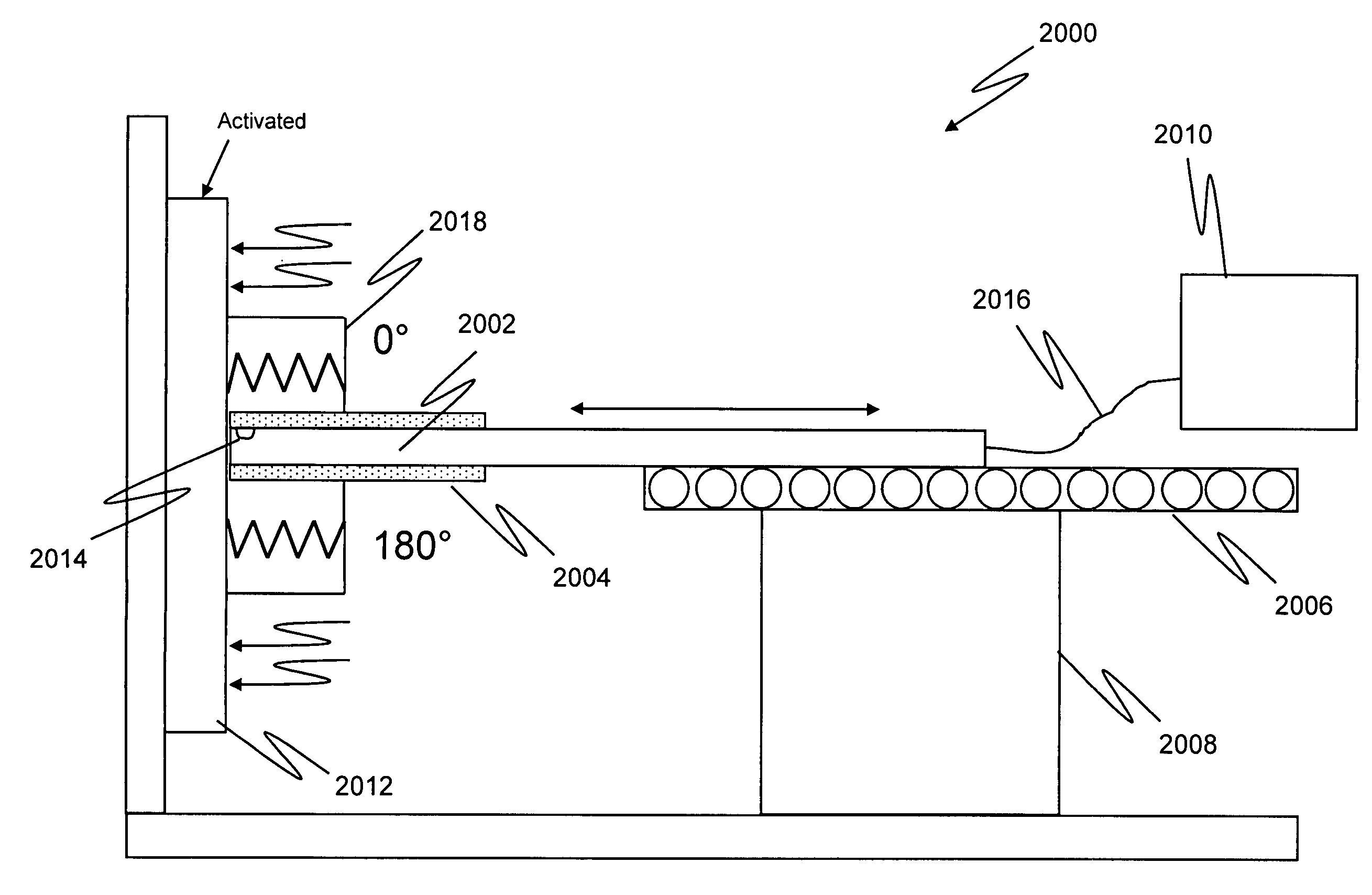
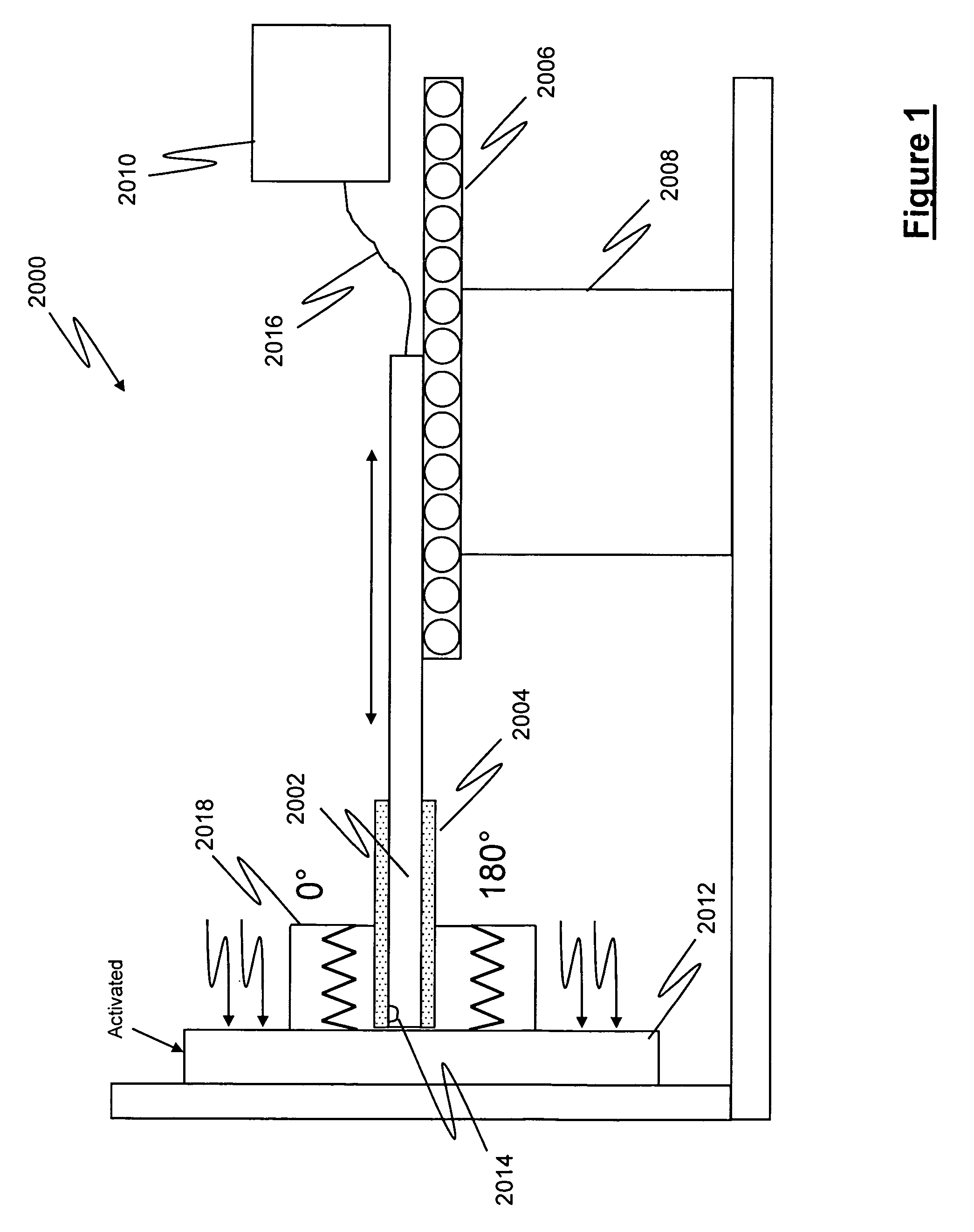
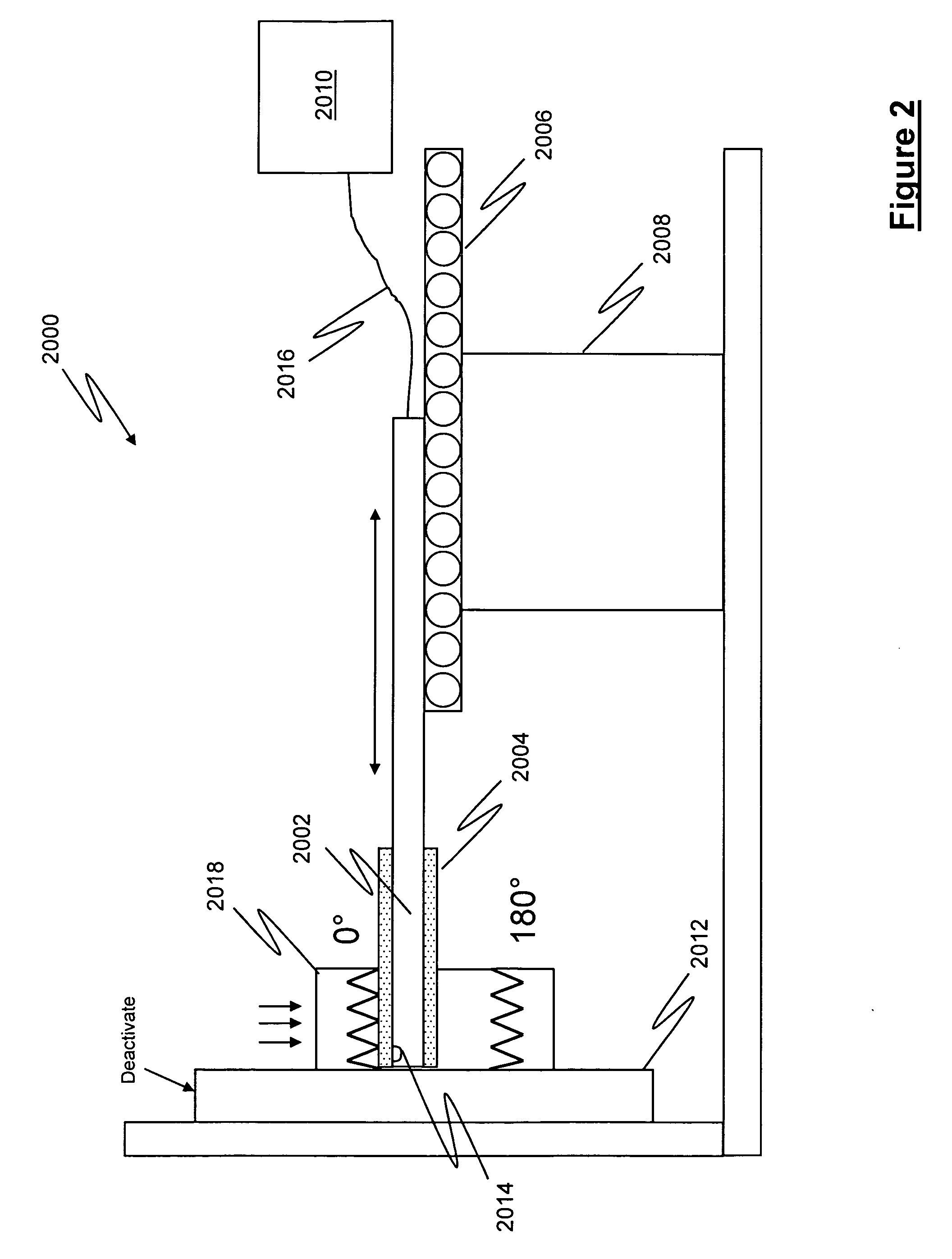
A system and method for measuring the threaded surface of an internally threaded component is provided, where the inspection system includes at least one measuring probe, wherein the at least one measuring probe includes an emitter and a receiver and is sized and shaped to be positionable adjacent at least a portion of the threaded surface at an offset distance, wherein the emitter is configured to emit electromagnetic energy that is incident upon the threaded surface to generate reflected electromagnetic energy responsive to the threaded surface and wherein the receiver is configured to receive at least a portion of the reflected electromagnetic energy and generate threaded surface data. A processing device is also provided, wherein the processing device is in signal communication with the measuring probe to receive the threaded surface data and process the threaded surface data to determine physical characteristics of the threaded surface.

Description

RELATED APPLICATIONS[0001]This application is related to and claims priority from U.S. Provisional Patent Application Ser. No. 61 / 134,497 filed Jul. 10, 2008 entitled “Internal Inspection System and Method for implementing same”, the contents and disclosure of which is incorporated herein by reference in its entirety. Additionally, the invention disclosed herein is related to U.S. application Ser. No. 12 / 383,141 filed Mar. 20, 2009 entitled “Inspection System and Method for implementing same,” the contents and disclosure of which is incorporated herein by reference in its entirety.FIELD OF THE INVENTION[0002]This disclosure relates generally to a method and system for inspecting components and more particularly to a method and system for optically inspecting the internal physical characteristics of internally threaded components, such as nuts and other internally threaded components having varied configurations.BACKGROUND OF THE INVENTION[0003]As society becomes increasingly reliant...

Claims


Application Information

Patent Timeline
IPC IPC(8): G01B11/24G06F15/00
CPCG01B7/13G01B7/148G01B11/2425G01B11/12G01B7/284
Inventor JOHNSON, STANLEY P.
Owner QUEST INTEGRATED LLC
Learn More