Sensor device for and a method of sensing particles

Active Publication Date: 2010-05-06
SIEMENS HEALTHINEERS NEDERLAND BV
View PDF13 Cites 16 Cited by
  • Summary
  • Abstract
  • Description
  • Claims
  • Application Information

AI Technical Summary

Benefits of technology

[0020]According to an exemplary embodiment of the invention, a sensor apparatus may be provided in which the presence of particles in a sample may be detected qualitatively or quantitatively based on measuring a detection signal, more particularly a change of the detection signal with time, wherein a disturbing influence of viscosity modifications in the sample may be suppressed or even eliminated by correcting the detection signal on the basis of a (for instance pre-known) correlation between viscosity and change of the signal. In other words, the (change in the) sensor signal may be not only proportional to the concentration of the particles but may also depend on parameters such as transport rates within the sample which, in turn, may depend on the viscosity of the sample. When a pre-known correlation between a change of the sensor signal and the viscosity of the sample is taken into account and when the viscosity value is measured, the correction unit may be capable of calculating a modified / corrected / calibrated sensor signal being less sensitive or even essentially independent of the viscosity of the sample. Therefore, the measurement accuracy may be significantly improved.
[0070]The sensor device may be adapted for sensing the magnetic particles based on an effect of the group consisting of GMR, AMR, and TMR. Particularly, a magnetic field sensor device may make use of the Giant Magnetoresistance Effect (GMR) being a quantum mechanical effect observed in thin film structures composed of alternating (ferro)magnetic and non-magnetic metal layers. The effect manifests itself as a significant decrease in resistance from the zero-field state, when the magnetization of adjacent (ferro)magnetic layers are antiparallel due to a weak anti-ferromagnetic coupling between layers, to a lower level of resistance when the magnetization of the adjacent layers align due to an applied external field. The spin of the electrons of the nonmagnetic metal align parallel or antiparallel with an applied magnetic field in equal numbers, and therefore suffer less magnetic scattering when the magnetizations of the ferromagnetic layers are parallel. Examples for biosensors making use of the Giant Magnetoresistance Effect (GMR) are disclosed in WO 2005 / 010542 or WO 2005 / 010543.

Problems solved by technology

However, sufficient accuracy of measurement results may still be problematic under certain circumstances.

Method used


Image

  • Sensor device for and a method of sensing particles
  • Sensor device for and a method of sensing particles
  • Sensor device for and a method of sensing particles

Examples


Embodiment Construction

[0081]The illustration in the drawing is schematically. In different drawings, similar or identical elements are provided with the same reference signs.

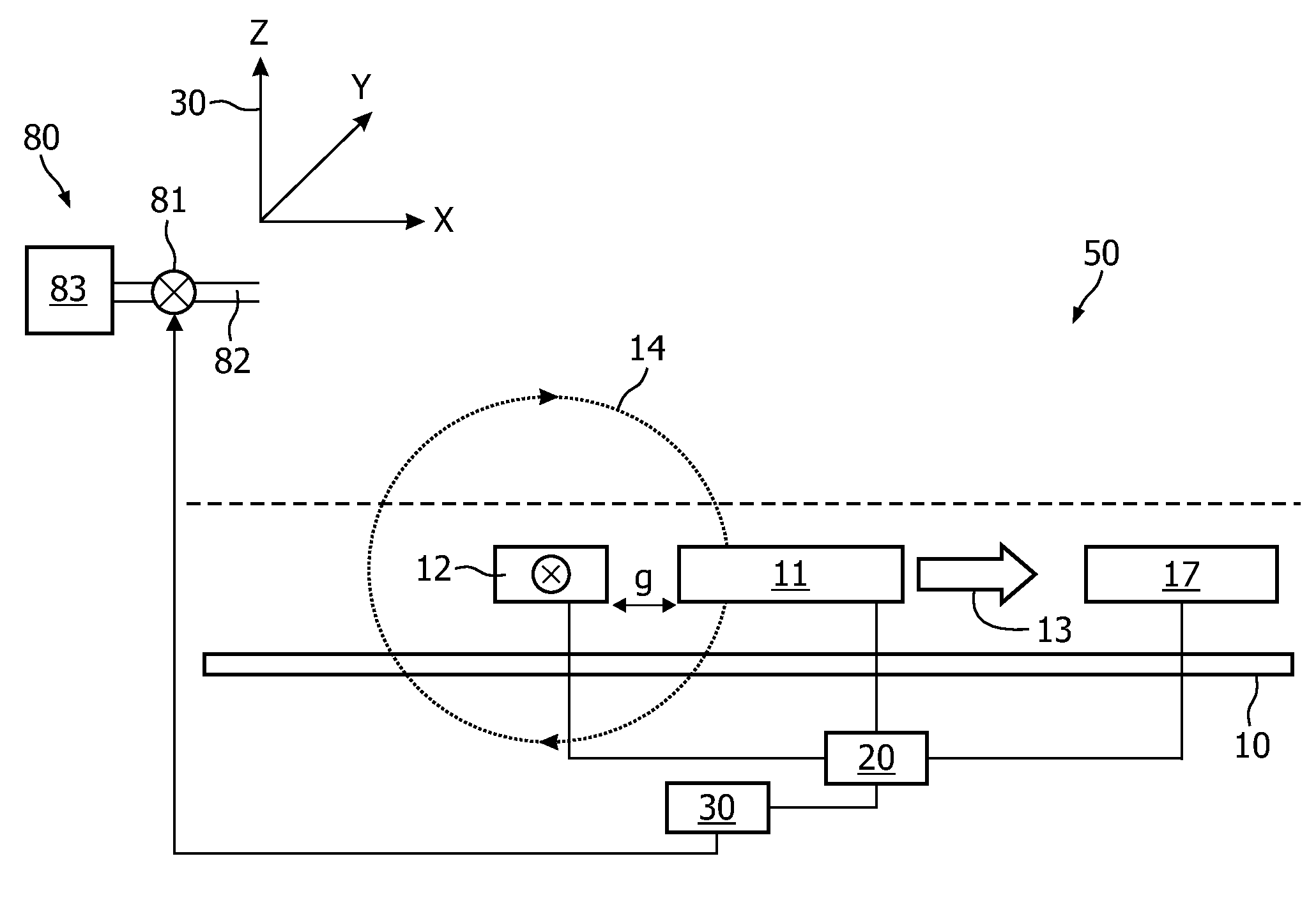
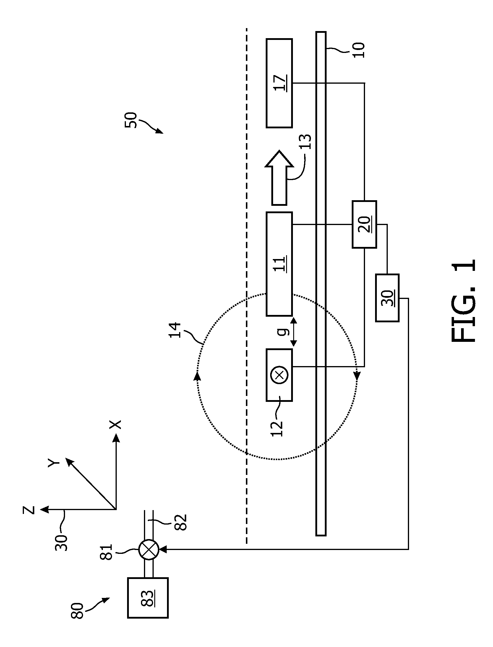
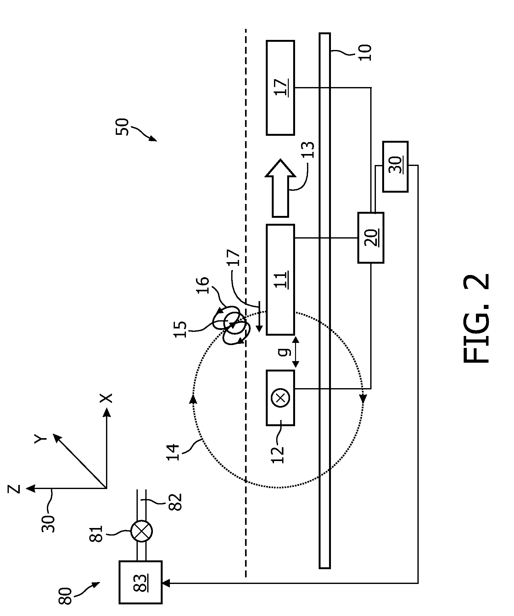
[0082]The device 50 according to an embodiment of the present invention is a biosensor and will be described with respect to FIG. 1 and FIG. 2.

[0083]The biosensor 50 detects magnetic particles 15 in a sample such as a fluid, a liquid, a gas, a visco-elastic medium, a gel or a tissue sample. The magnetic particles 15 can have small dimensions. With nano-particles are meant particles having at least one dimension ranging between 1 nm and 10000 nm, preferably between 10 nm and 3000 nm, more preferred between 100 nm and 1000 nm. The magnetic particles 15 can acquire a magnetic moment due to an applied magnetic field (for instance they can be paramagnetic). The magnetic particles 15 can be a composite, for instance consist of one or more small magnetic particles 15 inside or attached to a non-magnetic material. As long as the particles 15...


PUM


Abstract

A sensor device (50) for sensing particles (15) of a sample, the sensor device (50) comprising a sensing unit (11, 20) adapted for sensing a detection signal indicative of the presence of the particles (15), a viscosity measurement unit (11, 17, 20) adapted for measuring the viscosity of the sample, and a correction unit (20, 30) adapted for correcting the detection signal based on the measured viscosity.

Description

FIELD OF THE INVENTION[0001]The invention relates to a sensor device.[0002]The invention further relates to a method of sensing particles.[0003]Moreover, the invention relates to a program element.[0004]Further, the invention relates to a computer-readable medium.BACKGROUND OF THE INVENTION[0005]A biosensor may be a device for the detection of an analyte that combines a biological component with a physicochemical or physical detector component.[0006]Magnetic biosensors may use the Giant Magnetoresistance Effect (GMR) for detecting biological molecules being magnetic / magnetisable or being labeled with magnetic / magnetisable beads.[0007]In the following, biosensors will be explained which may use the Giant Magnetoresistance Effect.[0008]WO 2005 / 010542 discloses the detection or determination of the presence of magnetic particles using an integrated or on-chip magnetic sensor element. The device may be used for the magnetic detection of the amount of binding of biological molecules on a...

Claims


Application Information

Patent Timeline
IPC IPC(8): G01N27/74
CPCB82Y25/00G01N15/0656G01N2011/008G01N2015/0053G01R33/093G01R33/12G01R33/1284
Inventor NIEUWENHUIS, JEROEN HANSVERHOECKX, GODEFRIDUS JOHANNESPRINS, MENNO WILLEM JOSEVAN LANKVELT, PETRUS JOHANNES WILHELMUSVAN OMMERING, KIM
Owner SIEMENS HEALTHINEERS NEDERLAND BV
Why Eureka
Try Eureka