
Thermo-electric, rechargeable vehicle powering system

a technology of vehicle powering system and thermal energy, which is applied in the direction of electric propulsion mounting, battery/cell propulsion, transportation and packaging, etc., can solve the problem of quick depletion of electric energy storage section, achieve quick and efficient conversion, reduce the range requirement of batteries, and increase the energy density of molten salt technology

Inactive Publication Date: 2010-05-06
TULI RAJA SINGH
View PDF10 Cites 14 Cited by
  • Summary
  • Abstract
  • Description
  • Claims
  • Application Information

AI Technical Summary

Benefits of technology

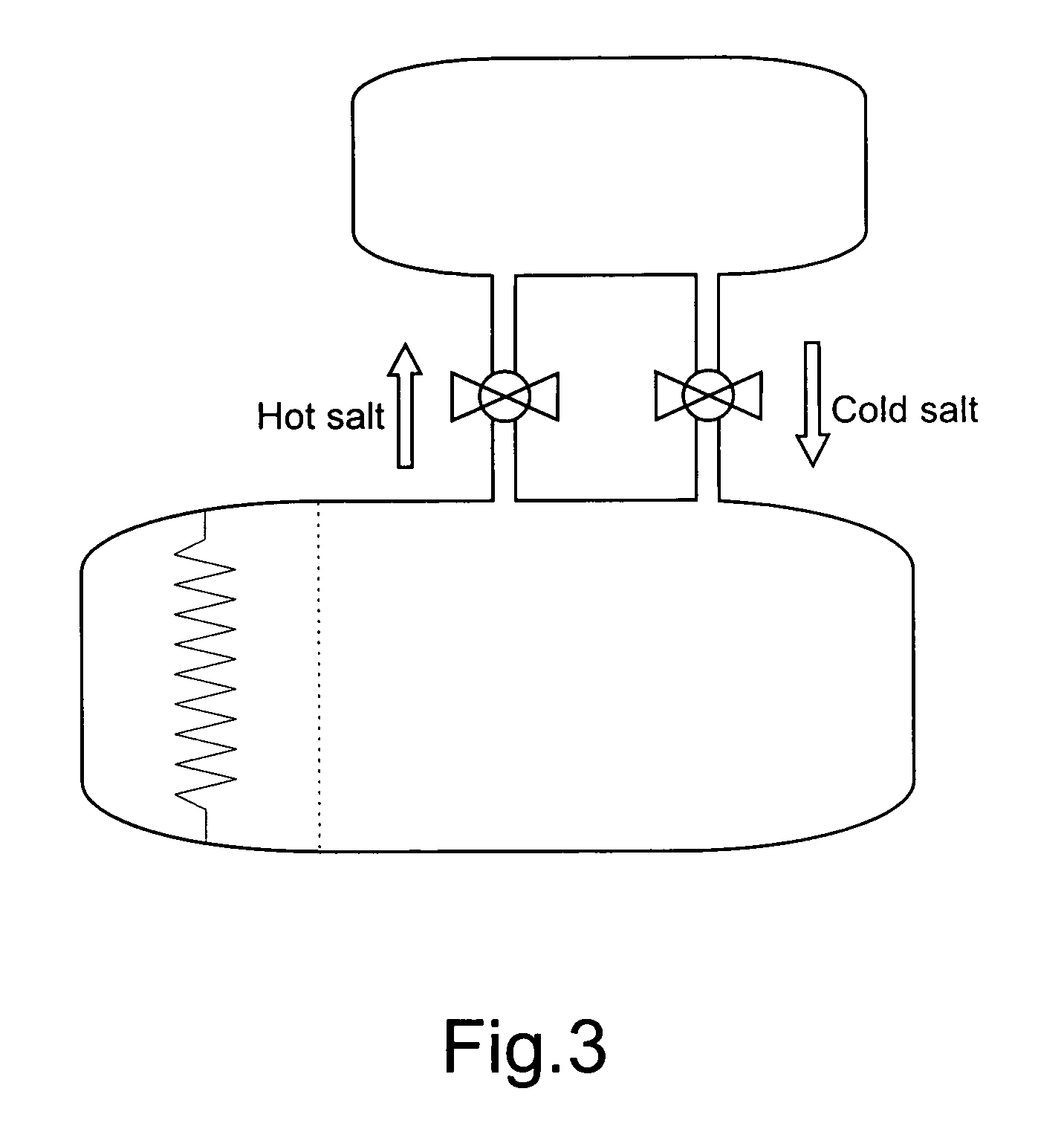
[0004]The present invention overcomes the limitations of the prior art regarding both conversion efficiency and range by storing the motive energy in the form of thermal energy, and then converting it to electric energy only as needed. For thermal energy storage it utilizes a container filled with a thermal energy storing material, for instance a salt. The higher energy density of the molten salt technology compared to the standard Lithium ion battery technology, associated with the quick and efficient conversion into electric energy to replenish the storage / driving battery reduces the range requirement for the battery to a level in which the current battery technology compromises neither the design of the vehicle nor its performance.
[0010]It is therefore an object of the present invention to provide means for regulating and stabilizing the electric energy output of the heat energy converter section, which is run intermittently.
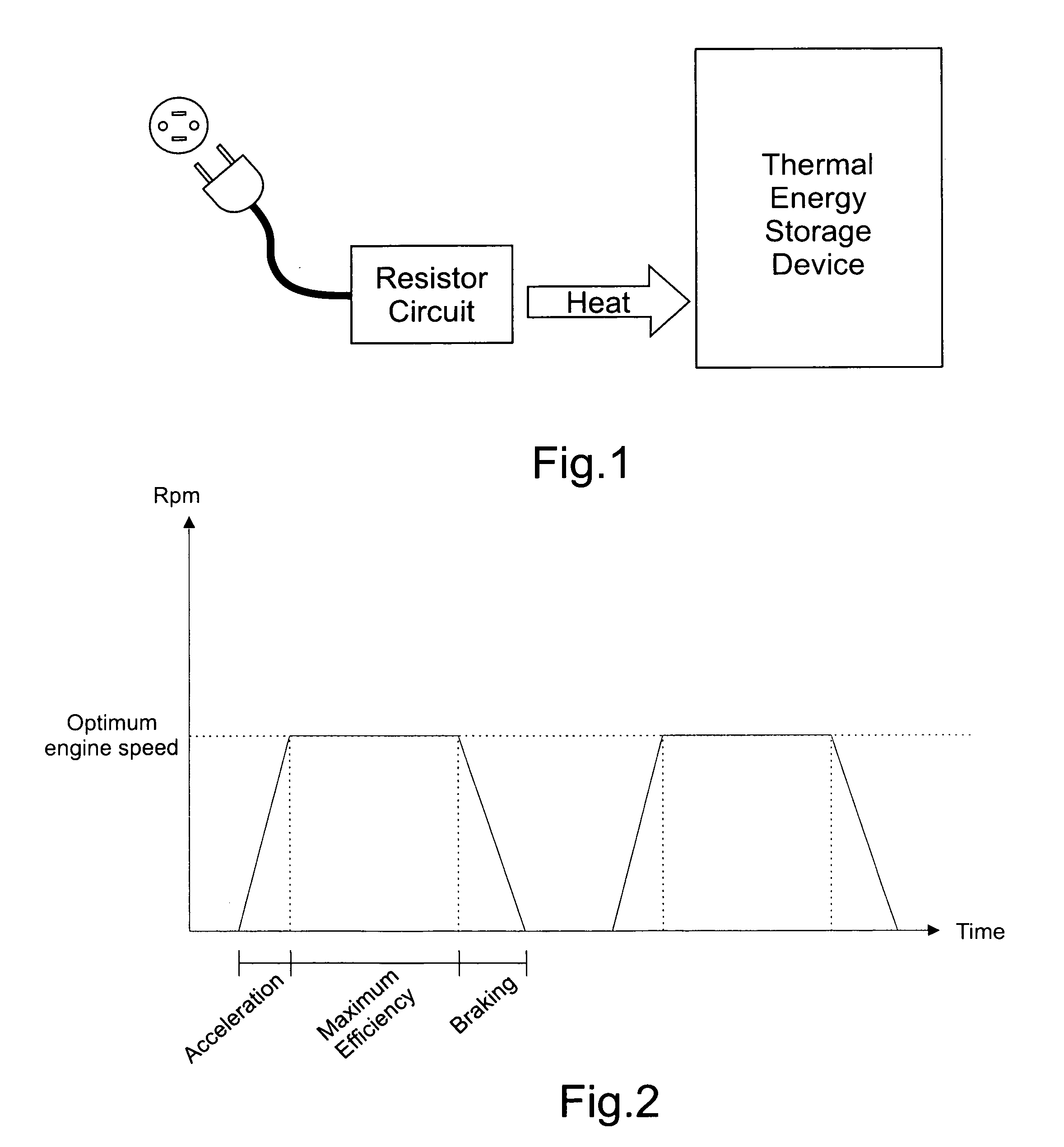
[0012]Another object of the present invention is to provide means for improving the efficiency of the thermal engine element integrated in the system by regulating its operational regime.

Problems solved by technology

However upon accelerating the electric motors demand approximately 120 KWh for a short period of time, causing a quick depletion of the electric energy storage section.

Method used


Image

  • Thermo-electric, rechargeable vehicle powering system
  • Thermo-electric, rechargeable vehicle powering system
  • Thermo-electric, rechargeable vehicle powering system

Examples


Embodiment Construction

[0019]The system of the present invention combines a thermal energy storage section, a heat energy converter section and an electric energy storage section in the same vehicle, with the wheels being ultimately propelled by electric motors. These sections are now described in order, addressing each of their elements.

[0020]The thermal energy storage section utilizes an external energy source to provide thermal energy to be transferred to a thermal energy storage device which is incorporated in the vehicle itself. The external energy source can be for instance a domestic electric power outlet connected to a resistor circuit that converts the electric energy input into heat output. Said arrangement is illustrated by FIG. 1. It can also be a domestic solar energy concentrator array, which has the advantage of avoiding the step of initial energy conversion from the power outlet's electric energy into thermal energy. The charging of the thermal energy storage device is typically performed ...


PUM


Abstract

The present invention generally relates to the technical field of motive power systems for automotive vehicles that convert stored thermal energy into electricity for energizing electric motors to drive a vehicle. The invention discloses several devices that integrate the vehicle powering system, including a programmable regulator, a thermal energy storage section, a heat energy converter section and an electric energy storage section. All said elements are incorporated in the same vehicle, with the wheels being ultimately propelled by electric motors. The combination of the devices disclosed results in improved efficiency in the conversion of input energy to drive a vehicle.

Description

FIELD OF THE INVENTION[0001]The present invention generally relates to the technical field of motive power systems for automotive vehicles that convert stored thermal energy into electricity for energizing electric motors to drive a vehicle.[0002]The invention discloses several devices that integrate the vehicle powering system, including a programmable regulator, a thermal energy storage section, a heat energy converter section and an electric energy storage section. All said elements are incorporated in the same vehicle, with the wheels being ultimately propelled by electric motors. The combination of the devices disclosed results in improved efficiency in the conversion of input energy to drive a vehicle.BACKGROUND OF THE INVENTION[0003]The high energy density of thermal energy storage systems favors their use in vehicle propulsive systems. Unfortunately, the state of the art thermal vehicles have the inconvenience of low energy conversion efficiency. The state of the art electri...

Claims


Application Information

Patent Timeline
Patent Type & Authority Applications(United States)
IPC IPC(8): B60L11/00H01L35/00
CPCB60L2250/18B60W40/09B60L50/00Y02T10/7005B60L50/50Y02T10/646B60L50/60Y02T10/70Y02T10/64
Inventor TULI, RAJA SINGH
Owner TULI RAJA SINGH
Learn More