
Engine controller

a technology of engine controller and controller, applied in the direction of electrical control, process and machine control, etc., can solve the problems of exhaust gas transport delay and exhaust gas transport delay, and achieve the effect of inhibiting deterioration of exhaust gas property and increasing the chance of obtaining a learned valu

Inactive Publication Date: 2010-05-06
TOYOTA JIDOSHA KK
View PDF11 Cites 17 Cited by
  • Summary
  • Abstract
  • Description
  • Claims
  • Application Information

AI Technical Summary

Benefits of technology

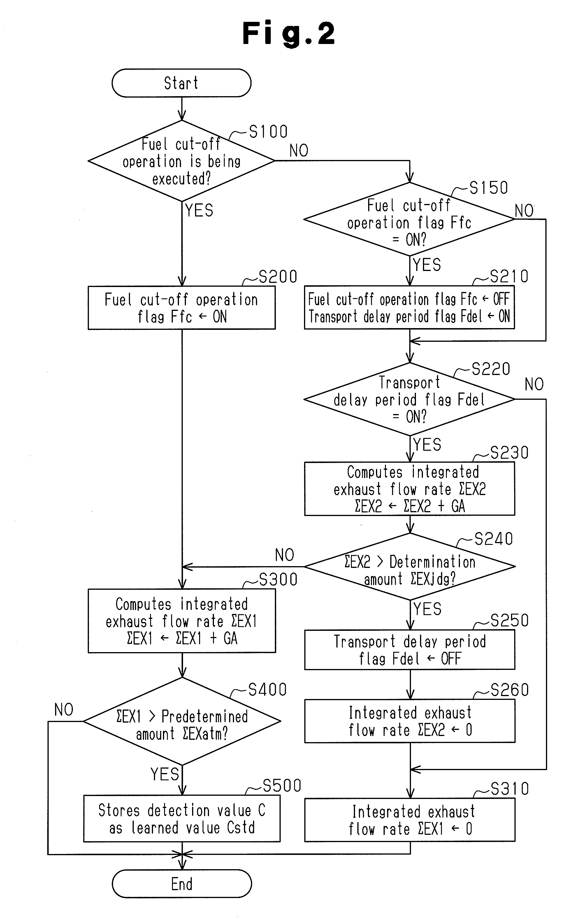
The present invention provides an engine controller that increases the chances of learning a reference value for an oxygen concentration sensor and inhibits deterioration of exhaust gas property due to variation of the detection value of the oxygen concentration sensor. The learning process is executed by an oxygen concentration sensor located in the exhaust passage of the engine. The learning process is continued until a predetermined time period has passed after the fuel cut-off operation is terminated. This allows for a longer learning process compared to conventional methods, increasing the likelihood of obtaining a learned value. The learning process is also based on the exhaust gas transport delay, which occurs due to the air drawn into the engine during the fuel cut-off operation. The learning means preferably prohibits the learning process if the deviation between the reference value and the detection value of the oxygen concentration sensor is great. The integrated exhaust flow rate from when the fuel cut-off operation is started is used to determine whether the ambient air is equal to the atmospheric state. This helps to accurately determine the reference value and prevents incorrect learning based on the sensor's output property.

Problems solved by technology

Thus, an exhaust gas transport delay occurs even after the termination of the fuel cut-off operation until the burned gas reaches the vicinity of the oxygen concentration sensor.
The exhaust gas transport delay is caused based on the fact that the air drawn into the engine during the fuel cut-off operation and fed unchanged to the exhaust passage flows.

Method used


Image

  • Engine controller
  • Engine controller
  • Engine controller

Examples


first embodiment

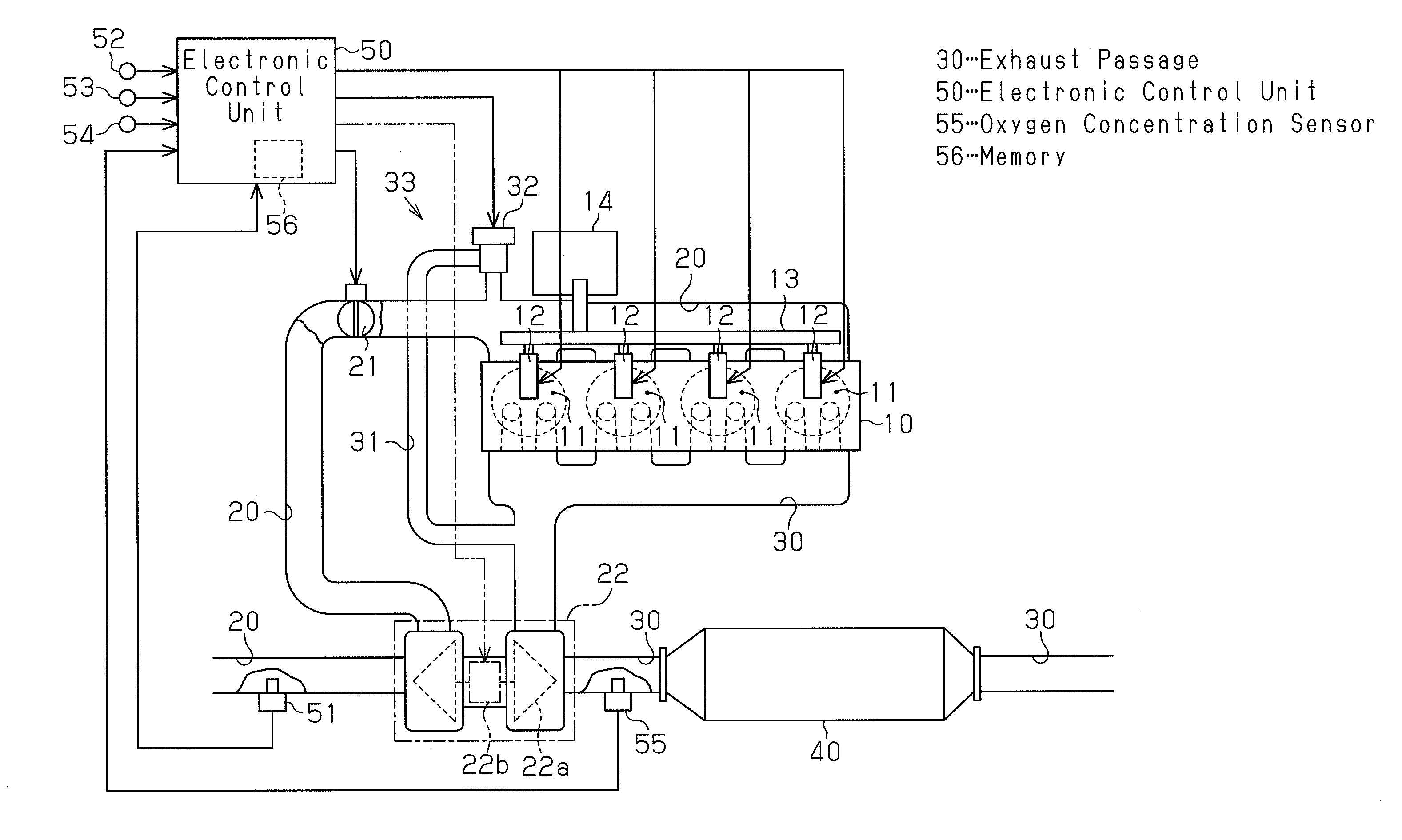
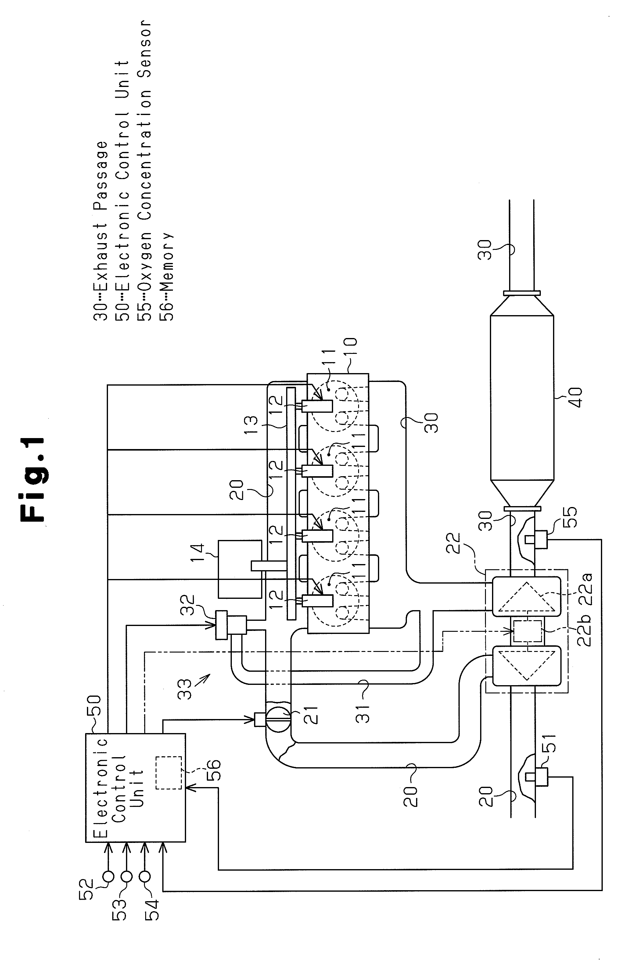
[0037]An engine controller according to a first embodiment of the present invention will now be described with reference to FIGS. 1 to 3. The controller of the first embodiment is applied to a diesel engine.

[0038]As shown in FIG. 1, an intake passage 20 and an exhaust passage 30 are connected to an engine main body 10. An intake throttle valve 21, which is selectively opened and closed by a motor, is provided in the intake passage 20. The amount of air introduced into combustion chambers 11 is adjusted by changing the opening degree of the intake throttle valve 21.

[0039]Injectors 12, which inject fuel, are provided in the combustion chambers 11 of the engine main body 10 such that each injector 12 corresponds to one of cylinders. The injectors 12 are connected to a common rail 13. Fuel that is supplied to the common rail 13 is injected into the combustion chambers 11 from the injectors 12. Fuel that is pressurized by a supply pump 14 is supplied to the common rail 13.

[0040]The intak...

second embodiment

[0088]An engine controller according to a second embodiment of the present invention will now be described with reference to FIGS. 1, 5, and 6. The controller of the second embodiment is applied to a diesel engine. The structure of the diesel engine according to the present embodiment differs from the structure of the diesel engine according to the first embodiment in only part of the structure of the turbocharger 22. Thus, like members are given like numbers and detailed explanations are omitted.

[0089]As shown by the chain double-dashed line in FIG. 1, the turbocharger 22 includes a motor 22b, which drives a turbine 22a. The electronic control unit 50 controls drive force of the motor 22b in accordance with the engine operating condition detected by the various types of sensors 51 to 55. The drive force of the motor 22b assists rotation of the turbine 22a and inhibits deterioration of the supercharging efficiency even in a low engine speed range, where the flow rate of exhaust gas ...

third embodiment

[0108]An engine controller according to a third embodiment of the present invention will now be described with reference to FIGS. 7 and 8. The controller of the third embodiment is applied to a diesel engine. The third embodiment is a combination of the first embodiment and the second embodiment. Since the structure of the diesel engine according to the third embodiment is the same as that of the second embodiment, like or the same reference numerals are given to the components of the diesel engine, and detailed explanation is omitted.

[0109]Learning process of the oxygen concentration sensor 55 will now be described with reference to FIG. 7. In the learning process according to the present embodiment, the process of the second embodiment in which the turbocharger 22 is forcibly driven by the motor 22b during the fuel cut-off operation is added to the learning process of the first embodiment. Thus, the same reference numerals are given to those steps that are the same as the steps of...


PUM


Abstract

An electronic control unit 50 determines whether the ambient air in the vicinity of an oxygen concentration sensor 55 in an exhaust passage 30 has become equal to the atmospheric state as a fuel cut-off operation is executed. If the ambient air in the vicinity of the oxygen concentration sensor 55 is equal to the atmospheric state, the electronic control unit 50 executes a learning process, in which a detection value C of the oxygen concentration sensor55 is stored as a learned value Cstd in a memory 56. The electronic control unit 50 continues the learning process until a predetermined time period set based on an exhaust gas transport delay elapses from when the fuel cut-off operation is terminated.

Description

FIELD OF THE INVENTION[0001]The present invention relates to an engine controller that includes an oxygen concentration sensor located in an exhaust passage. The oxygen concentration sensor detects the concentration of oxygen in exhaust gas.BACKGROUND OF THE INVENTION[0002]A typical gasoline engine executes air-fuel ratio feedback control to correct fuel injection amount based on a detection value from the oxygen concentration sensor located in the exhaust passage. To improve the exhaust gas property, diesel engines have been proposed that are configured to control exhaust gas recirculation amount by an exhaust gas recirculation mechanism, that is, an EGR mechanism based on the oxygen concentration of exhaust gas detected by the oxygen concentration sensor located in the exhaust passage.[0003]However, as shown in FIG. 9, the actual output property of the oxygen concentration sensor, that is, the relationship between the oxygen concentration and a detection value C can deviate from t...

Claims


Application Information

Patent Timeline
Patent Type & Authority Applications(United States)
IPC IPC(8): F02D41/00
CPCF01N3/035F02B37/10F02B39/10F02B2275/14F02D41/123F02D41/1454F02D41/2441F02D41/2448F02D41/2454F02D41/2474Y02T10/144F02M26/05Y02T10/12
Inventor ENOMOTO, HIROSHIMORIKAWA, ATSUSHI
Owner TOYOTA JIDOSHA KK
Learn More