
Weight checking conveyor with adjustable infeed section

a conveyor and infeed section technology, applied in the direction of weighing devices, measuring devices, instruments, etc., can solve the problems of lack of adjustable infeed section and substantially horizontal scale section accuracy, inaccurate weighing proportion, and inconvenient operation

Inactive Publication Date: 2010-04-29
DALE CHRISTOPHER
View PDF17 Cites 9 Cited by
  • Summary
  • Abstract
  • Description
  • Claims
  • Application Information

AI Technical Summary

Benefits of technology

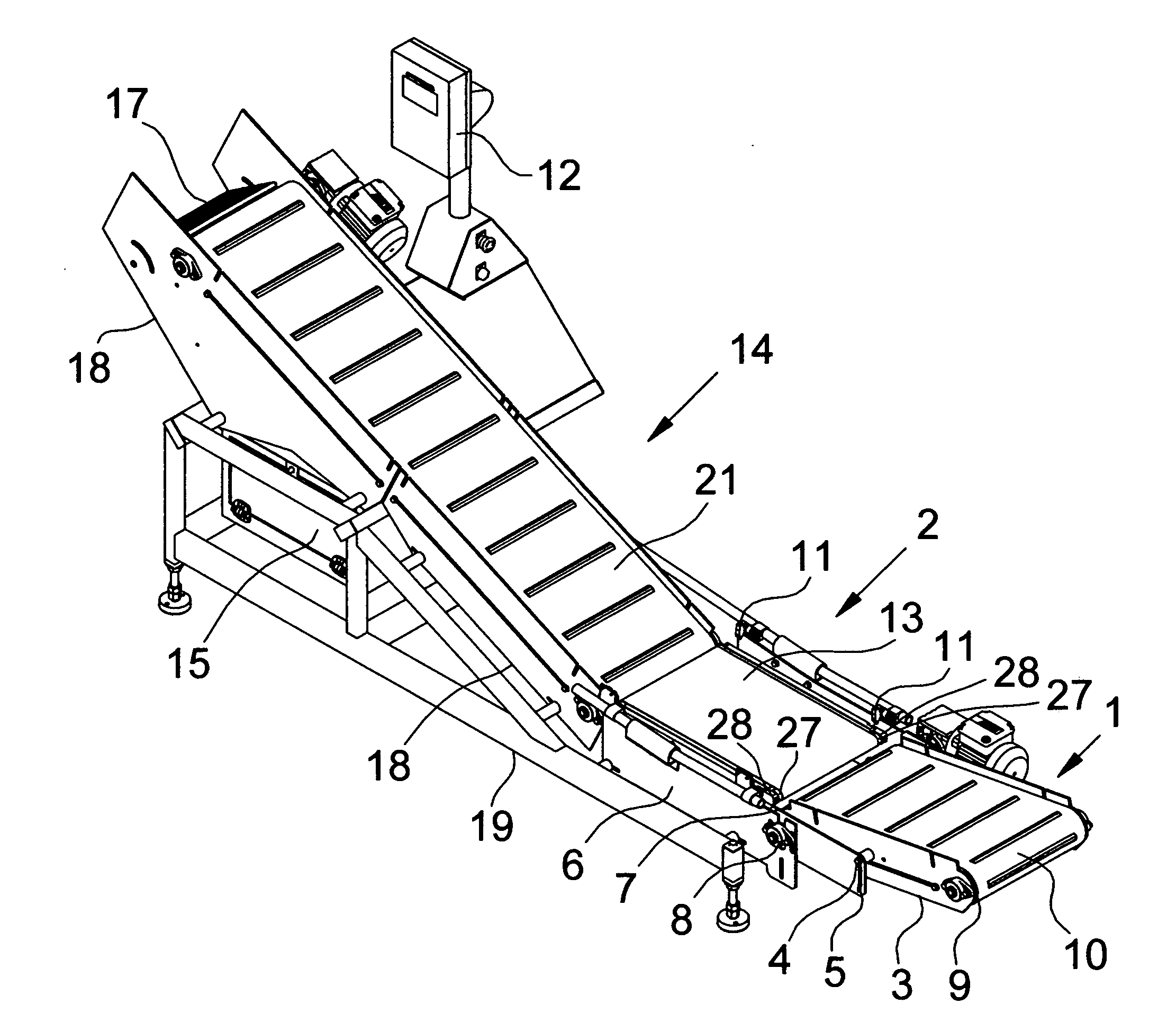
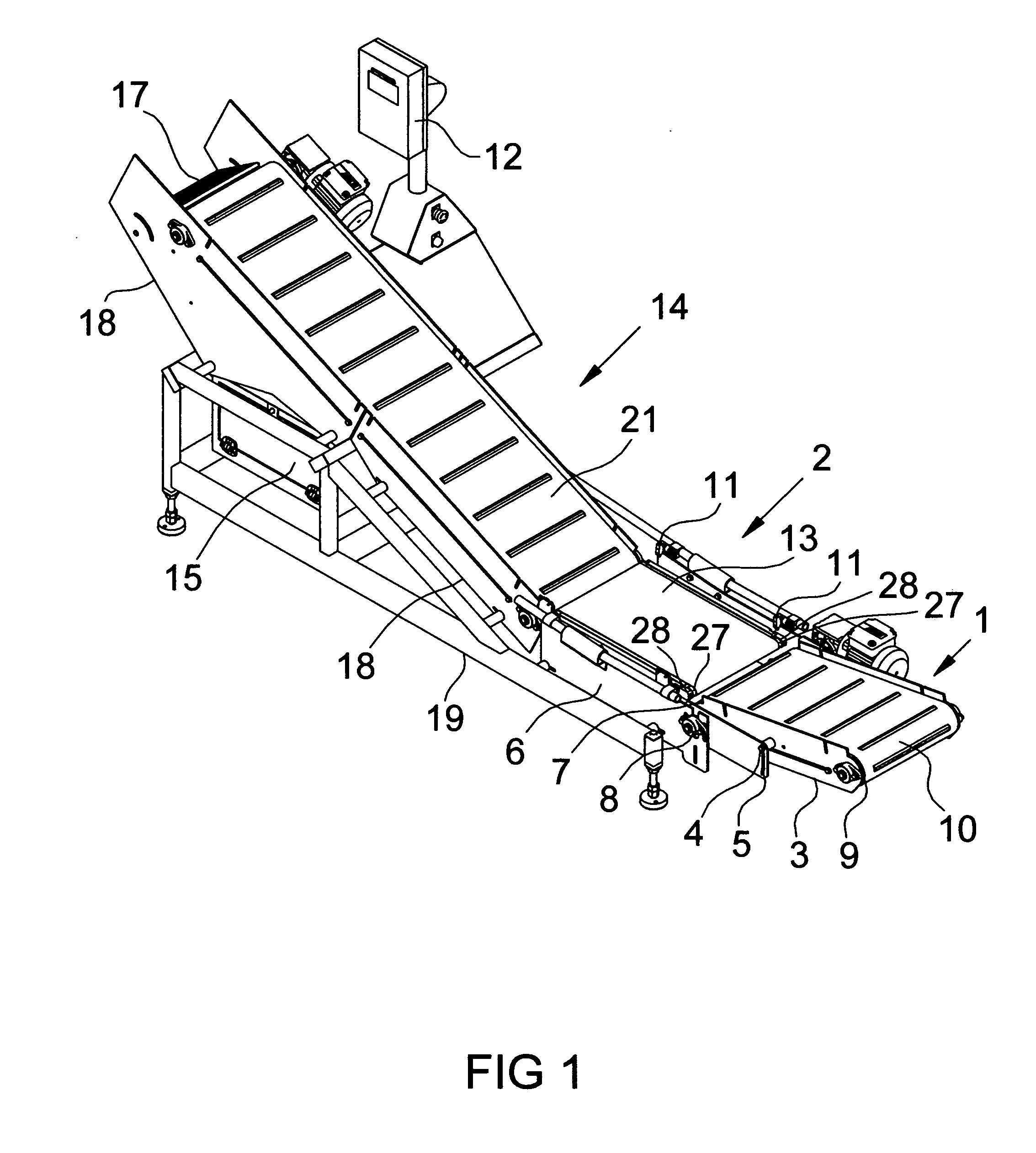
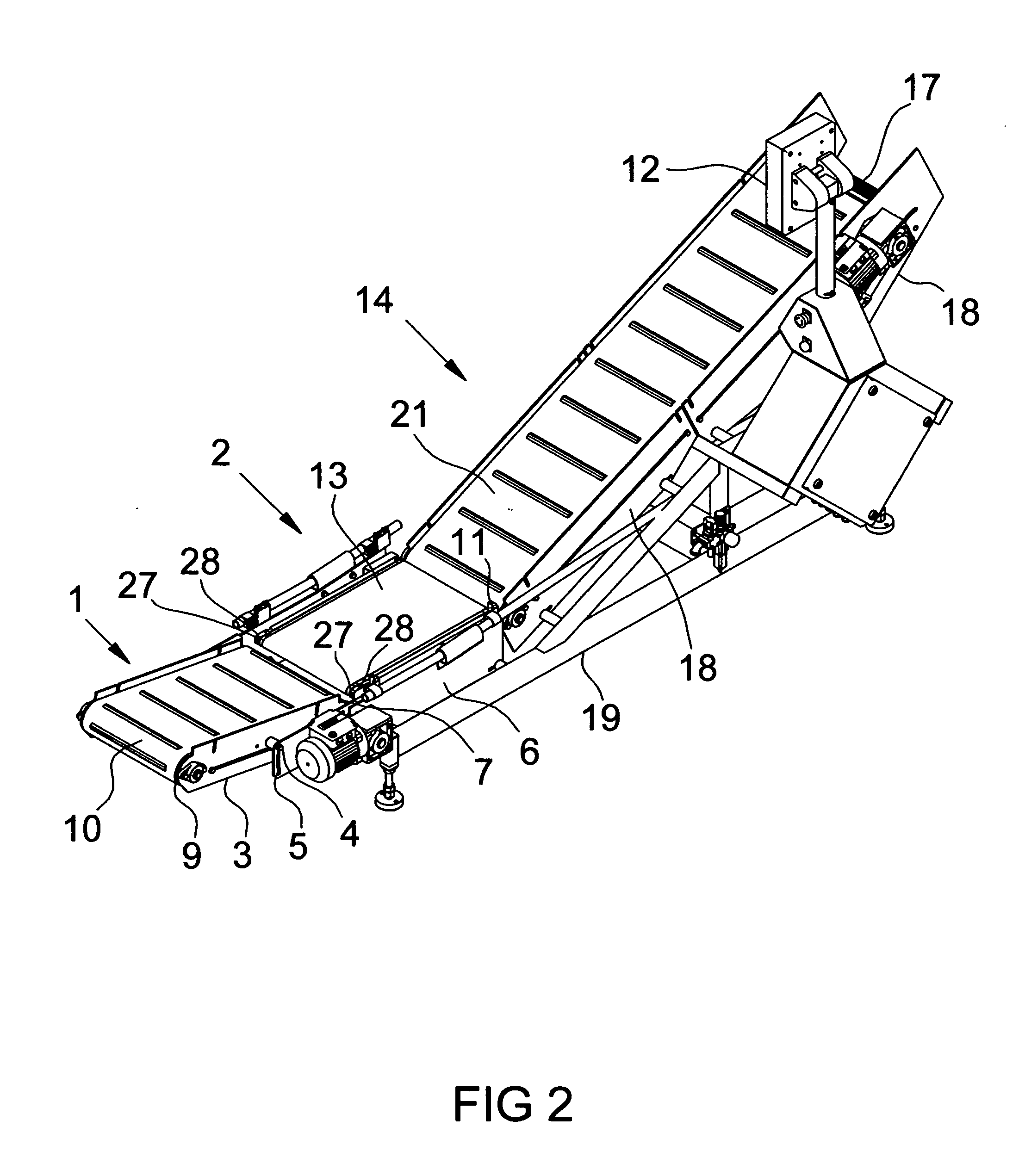
[0013]In accordance with one embodiment a weight checking conveyor with adjustable infeed section comprises three conveyor sections, an infeed section, a check weighing section, and an outfeed or take-away section. The infeed conveyor section is pivotably mounted to a horizontal weight checking conveyor. The angle of the infeed section may be increased to allow positioning under a vertical form fill and seal bag making machine, or decreased to prevent product damage as it falls from the bag making machine. The check weighing conveyor section is preferably horizontal to increase weighing accuracy. The outfeed conveyor section is preferably inclined to deliver finished product to a manageable working height for personnel packing product into shipping cartons.

Problems solved by technology

If the finished bags hit a horizontal conveyor when they drop from a bag machine, some bagged items tend to shift within the bag causing a portion of it to be inaccurately weighed.
U.S. Pat. No. 4,788,930 to Matteau (1988) shows an inclined conveyor which reduces the horizontal space needed for installation, but lacks the adjustable infeed section and the accuracy of a substantially horizontal scale section.
This position may cause damage to finished bags due to the vertical drop as well as increasing the functional height of the conveyor system.
The check weighers described in U.S. Pat. No. 3,379,234 to Kasper (1968), U.S. Pat. No. 3,484,813 to Davies (1969), and U.S. Pat. No. 4,065,911 to Fagan (1978) describe improvements primarily to the scale control, but do not address the problem of clearance below a bag making machine.
Although this invention could be made shorter to allow for clearance between the floor and the bag machine, it lacks the adjustability required to adapt to varying bag lengths and machine types.

Method used


Image

  • Weight checking conveyor with adjustable infeed section
  • Weight checking conveyor with adjustable infeed section
  • Weight checking conveyor with adjustable infeed section

Examples


Embodiment Construction

[0022]One embodiment of the weight checking conveyor with adjustable infeed section is shown in FIG. 1. The infeed section 1 transports products such as packaged food from a vertical form, fill, and seal machine to the check weighing section 2. The infeed section frame 3 is adjustable to allow it to fit below the exit guards (not shown) of the bag making machine. The pitch or height adjustment is made using an adjustment bolt 4. This adjustment bolt 4 fits through the arc shaped slot 5 in the check weighing section frame 6 to hold the infeed section frame 3 to the check weighing section frame 6. The infeed section frame 3 is allowed to pivot about the same axis as the infeed drive roller 7 using flange mounted bearings 8 fastened to the check weighing section frame 6. Since there are preferably no supports leading from the infeed section 1 of the conveyor to the ground, the infeed idler roller 9 and infeed conveyor belt 10 are able to be placed at nearly floor level reducing the nee...


PUM


Abstract

An automatic conveyor comprising an angularly adjustable infeed, check weighing, and take-away sections. The conveyor relies on a pivotal infeed section with no frontal supporting structure to reduce the clearance required between a bag making machine and the conveyor. The check weighing section is controlled by a photoelectric eye before and after the check weighing section. A signal from the check weigher instructs the inclined takeaway section to accept or reject the weighed product using a deflecting plate to dispense or contain the product in a secure holding area.

Description

CROSS REFERENCE TO RELATED APPLICATIONS[0001]This application claims the benefit of provisional patent application Ser. No. 61 / 197,354, Filed 2008 Oct. 27 by the present inventor.FEDERALLY SPONSORED RESEARCH[0002]Not ApplicableSEQUENCE LISTING OR PROGRAM[0003]Not ApplicableBACKGROUND[0004]1. Field[0005]This application relates to check weighing conveyors, specifically those which are incorporated into an inclined take away conveyor to convey product from a bag making machine, such as a vertical form fill and seal machine.[0006]2. Prior Art[0007]When a package is made from a bag machine, the finished bag must be conveyed out from the underside of the machine to the check weigher. Ideally, the section of conveyor that the package first touches should be at nearly floor level. This low profile allows for clearance between the seal jaws of the bag machine to keep from deforming the bag as it exits the machine. Additionally, this first conveyor section should preferably be angled to assi...

Claims


Application Information

Patent Timeline
IPC IPC(8): G01G9/00
CPCG01G15/006
Inventor DALE, CHRISTOPHER
Owner DALE CHRISTOPHER
Learn More