Combustion air system for recovery boilers, burning spent liquors from pulping processes

a combustion air system and boiler technology, applied in the direction of pulp liquor regeneration, combustion types, lighting and heating apparatus, etc., can solve the problems of loss of boiler efficiency, overflow of sprayed liquor droplets, and high velocity “lift” in the furnace center, so as to reduce the amount of harmful emissions from the boiler furnace. , the effect of high velocity

Inactive Publication Date: 2010-04-29
ANDRIZ OY
View PDF16 Cites 2 Cited by
  • Summary
  • Abstract
  • Description
  • Claims
  • Application Information

AI Technical Summary

Benefits of technology

[0014]The present invention provides an improved air supply system of combustion air to a furnace of a recovery boiler. A secondary combustion air supply is provided in which either local and / or central upward gas flows having a high velocity compared to an average upward gas velocity are efficiently avoided. Another feature of the invention is to enable a constant penetration of combustion air into the boiler at different loading levels. A further feature of the invention is to produce a better mixing of black liquor and combustion air in the furnace. Further, an air jet projected from a wall towards the opposite wall may contribute to formation of black liquor deposits on a furnace wall, and according to a further feature of the invention black liquor droplets are prevented from being thrown to the furnace walls. The improved air supply arrangement of this invention is also designed to reduce the amount of harmful emissions from the boiler furnace. In connection with this invention, air can be other oxygen-containing gas, such as flue gas.

Problems solved by technology

The high velocity “lift” in the center of the furnace is especially harmful as it results in carry-over of the sprayed liquor droplets.
Too much excessive air, however, causes a loss in efficiency of the boiler and an increase in costs.
Mixing of black liquor and air is difficult because of the upflow of gas, which is formed in the center part of the boiler, through which it is difficult for the weak secondary air flow to penetrate.
This gas flow, also called a “droplet lift”, also catches black liquor particles flowing counter-currently downwards and carries them to the upper part of the boiler, where they stick to the heat surfaces of the boiler, thus causing fouling and clogging.
Thus, a zone of rapid flow is formed in the center part of the boiler, and this renders mixing of flue gases from the side of the flow very difficult to achieve.
Then the flue gas leaving the furnace contains higher amounts of residual CO and H2S, and the utilization of the furnace is less effective than would be possible.
A drawback of the described arrangement is a high vertical combustion area, reaching in extreme cases the bullnose of the furnace.
As this combustion area has a reducing atmosphere, at least locally, more expensive materials have to be used in the furnace to a higher position than would be needed if combustion took place lower in the furnace.
Other disadvantages of the air systems, where combustion takes place high up in the furnace include high furnace outlet temperature resulting in large convective heat transfer surfaces later in the boiler, lower temperature in the lower furnace, and more expensive layout.
The lower temperature in the lower furnace does not allow as high sulfidity without SO2 emissions as a combustion system having a higher lower furnace temperature does.

Method used


Image

  • Combustion air system for recovery boilers, burning spent liquors from pulping processes
  • Combustion air system for recovery boilers, burning spent liquors from pulping processes
  • Combustion air system for recovery boilers, burning spent liquors from pulping processes

Examples


Embodiment Construction

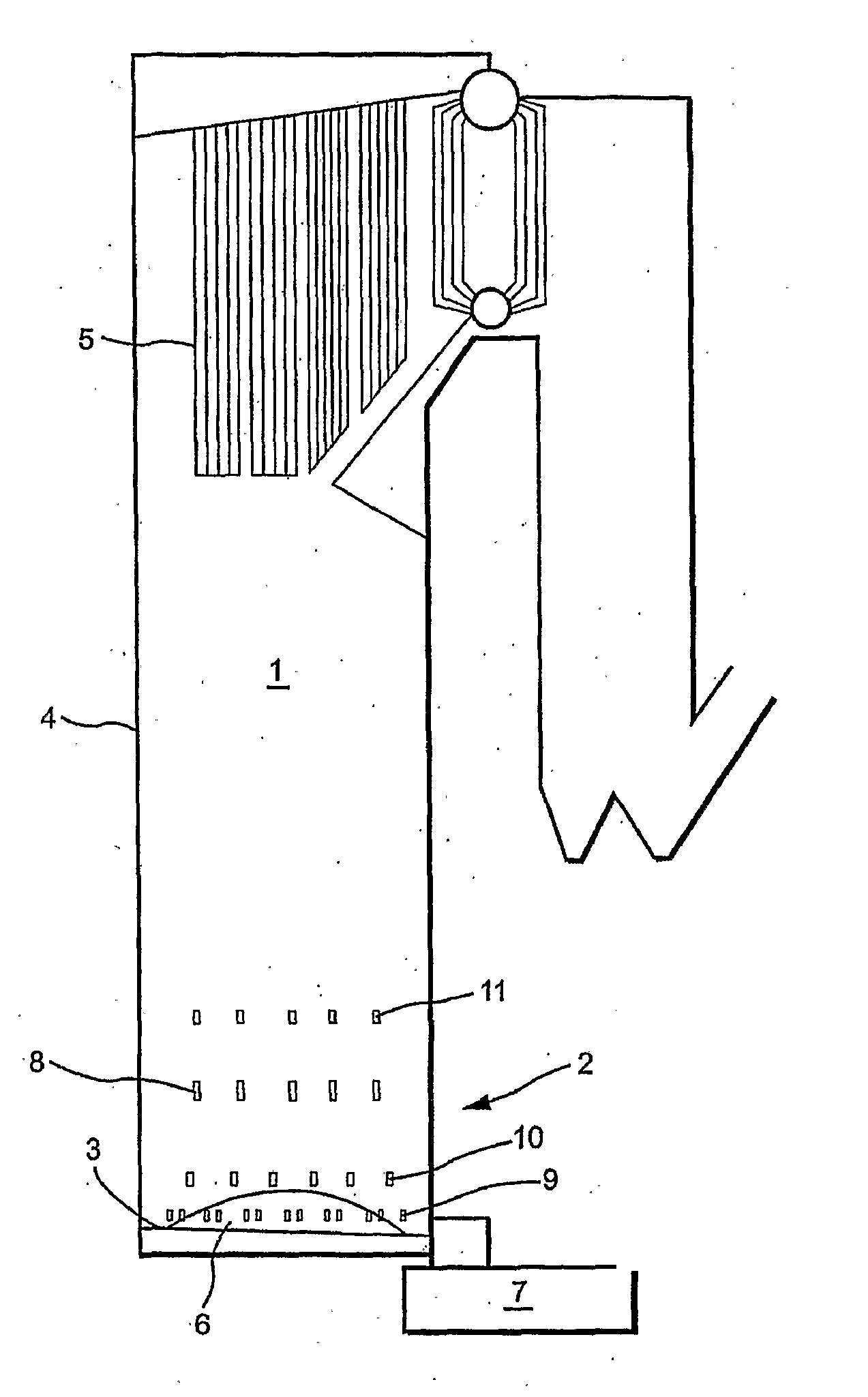
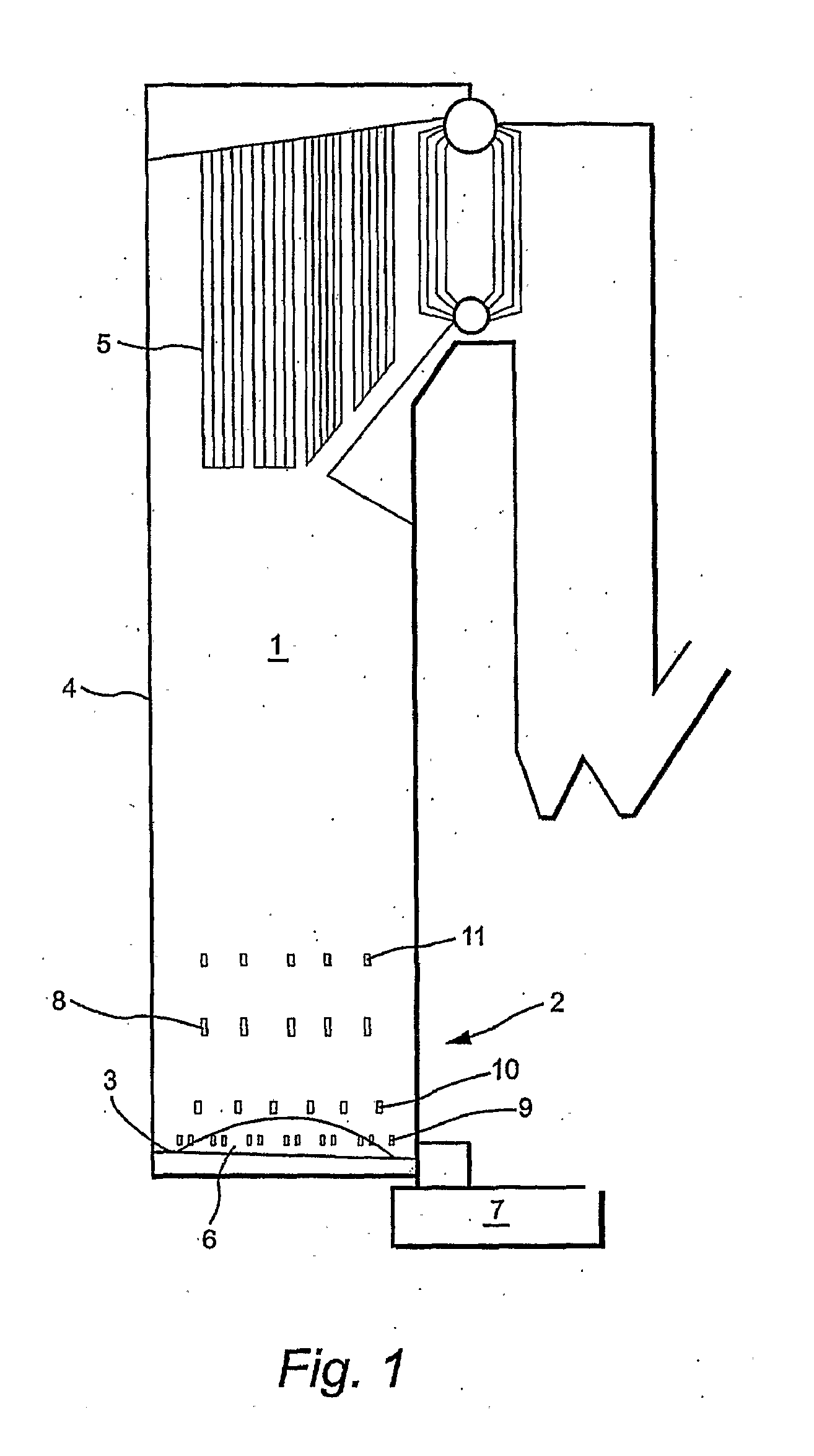
[0040]FIG. 1 illustrates a conventional recovery boiler. The boiler 1 comprises a furnace 2 provided with a bottom, boiler walls 4, and a super heater 5. In the combustion process, a bed of dried and partly burnt black liquor is formed at the bottom of the furnace. Melt chemicals flow through the porous bed to the bottom of the furnace, from where they are transferred as an overflow via melt chutes to a dissolving tank 7. Black liquor is introduced to the furnace through openings in zone 8. Air is introduced from three different levels: primary air ports 9, secondary air ports 10 and tertiary air ports 11.

[0041]As known, the recovery boiler furnace has a front wall, a rear wall and side walls. Black liquor spraying devices are disposed on these walls at one or several levels. A plurality of air ports are located on several horizontal levels on said walls for introducing air into the furnace from an air supply.

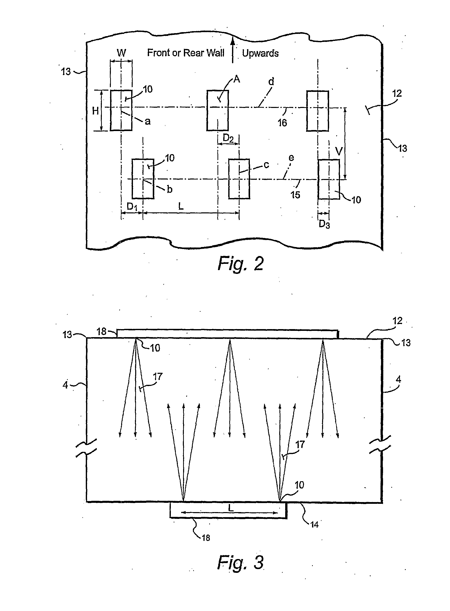
[0042]The air ports of the furnace for supplying secondary air are arrange...


PUM

PropertyMeasurementUnit
velocityaaaaaaaaaa
vertical distanceaaaaaaaaaa
residence timeaaaaaaaaaa

Abstract

An arrangement is disclosed for supplying an air jet form to the furnace of a recovery boiler, where the furnace has a front wall, a rear wall and side walls. Black liquor spraying devices are disposed on the furnace walls on one or several levels of the furnace. A plurality of air ports are located at several horizontal elevations for introducing air into the furnace from an air supply. In the arrangement for the secondary air flows, at least two horizontal air levels at different elevations are arranged above the lower primary levels and below the black liquor sprayer. Secondary air is supplied from two opposite walls. The secondary air ports on each of said first and second horizontal elevations comprise air ports for each horizontal elevation that project a pattern of large air jets into the furnace from said opposite walls and said secondary air ports further comprise a plurality of secondary air ports on at least one of the elevations that project smaller air jets into the furnace.

Description

FIELD OF THE INVENTION[0001]The present invention relates to an arrangement for supplying air in an air jet form to the furnace of a recovery boiler. The furnace has a front wall, a rear wall and side walls. Black liquor spraying devices are disposed on these walls at one or several levels. A plurality of air ports are located on several horizontal levels on said walls for introducing air into the furnace from an air supply. Specifically, the invention relates to an arrangement for organizing the secondary air flows below the black liquor spraying devices.BACKGROUND OF THE INVENTION[0002]An optimal supply of combustion air in the lower part of the furnace of a black liquor recovery boiler plays a considerable role in the control of a combustion process in the boiler.[0003]Since the chemical reactions in the kraft recovery boiler are very rapid, the speed of the process becomes substantially dependent on the mixing of combustion air and black liquor. This mixing step determines the b...

Claims


Application Information

Patent Timeline
Patent Type & Authority Applications(United States)
IPC IPC(8): F23G7/04F23L9/00
CPCD21C11/122F23L9/00F23G7/04
Inventor SAVIHARJU, KARISIMONEN, JORMAPAJU, RAIMOSAVOLAINEN, JUKKAVIHAVAINEN, ESA
Owner ANDRIZ OY
Why Eureka
Try Eureka