
Blade pitch management method and system

a blade pitch management and blade technology, applied in the direction of rotors, marine propulsion, vessel construction, etc., can solve the problems of reducing the efficiency of energy transfer, affecting the power production of wind turbines, and becoming increasingly difficult to control optimal energy capture, so as to reduce or eliminate aerodynamic stalls and low implemental costs

Active Publication Date: 2010-04-22
GENERAL ELECTRIC CO
View PDF31 Cites 54 Cited by
  • Summary
  • Abstract
  • Description
  • Claims
  • Application Information

AI Technical Summary

Benefits of technology

[0011]An advantage of the present disclosure includes reduction or elimination of aerodynamic stall due to icing, low density air operation, blade fouling, or other blade condition susceptible to aerodynamic stalling.
[0013]Another advantage of the present disclosure is that certain embodiments of the method include utilization of existing sensors and equipment, permitting retrofitting of wind turbines and low implemental cost.

Problems solved by technology

However, as blades have increased in size, it has become increasingly more difficult to control optimum energy capture.
Power production for a wind turbine is negatively impacted if the blades of the wind turbine operate in a non-optimal state.
Ice build-up on the wind turbine blades reduce the efficiency of energy transfer from the wind and may ultimately result in a aerodynamic stall from separation in airflow over the surface of the wing.
In addition to icing, other forms of blade fouling may occur.
For example, debris or insects may accumulate on the blades and reduce the aerodynamic efficiency of the blades.
In addition, low air density or a drop in air density may also result in a loss of energy transfer from the wind to the blades.
Aerodynamic stall causes a decrease in lift and an increase in drag coefficients for a wind turbine blade.
The onset of stall is signaled by a sharp change in a wind turbine's performance evident by degradation in output power versus expect power.
Power degradation resulting from the loss of energy transfer is most significant during periods of rated winds where full power output is anticipated by the controller.
The increasing the angle of attack by the control system of an aerodynamically stalled blade further increases the flow separation, increasing the stall condition and further decreasing the energy transfer from the wind.
As such, the current systems fail to address conditions, including icing conditions or similar conditions, such as low density air operation, blade fouling, or other blade condition susceptible to aerodynamic stalling.

Method used


Image

  • Blade pitch management method and system
  • Blade pitch management method and system
  • Blade pitch management method and system

Examples


example

[0031]FIG. 5 shows a graphical representation of a minimum pitch angle curve shown at the maximum Cp as a pitch angle according to an exemplary wind turbine control scheme. As shown in FIG. 5, in this example, the maximum power (Cp) point 500 along power curves 501 corresponding to the various tip speed ratios (i.e., tip speed ratios of 3.0, 4.0, 5.0, 6.0, 7.0, and 8.0, corresponding to TSR 3, TSR 4, TSR 5, TSR 6, TSR, 7 and TSR 8, respectively). These maximum power points 500 equal the minimum pitch angle setting for the wind turbine control according to embodiments of the disclosure. The maximum power points 500 are plotted to form a minimum pitch angle curve 503. As shown, the minimum pitch angle curve 503 provides wind turbine control such that operation on the left side region of the curve (i.e., “High AOA Stall” region), includes a high angle of attack blade and potential approach to stall, wherein the method of the present invention requires that the wind turbine maintain (an...


PUM


Abstract

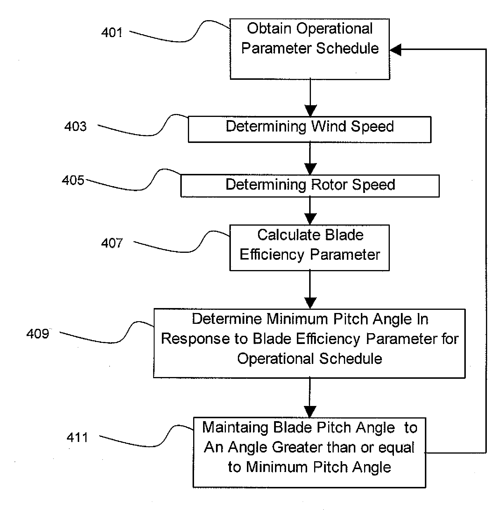
A method for operating a wind turbine. The method includes providing a wind turbine having at least one blade having adjustable pitch angle that is adjusted according to an operational parameter schedule. A blade efficiency parameter is determined in response to a wind speed and a rotor speed. A minimum pitch angle is determined in response to the blade efficiency parameter and the pitch angle of the at least one blade in response to the blade efficiency parameter is maintained to an angle equal to or greater than the minimum pitch angle independent of the operational parameter schedule. A wind turbine plant and a method for servicing a wind turbine are also disclosed.

Description

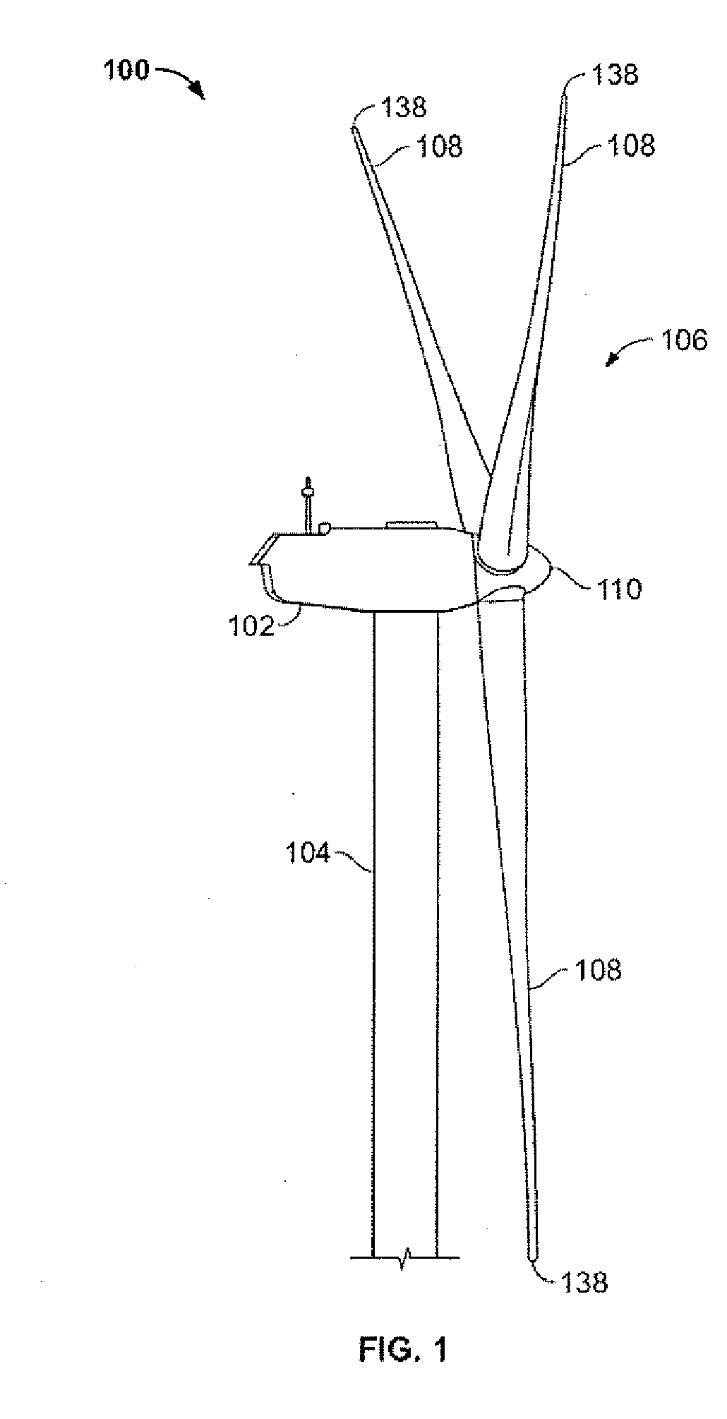
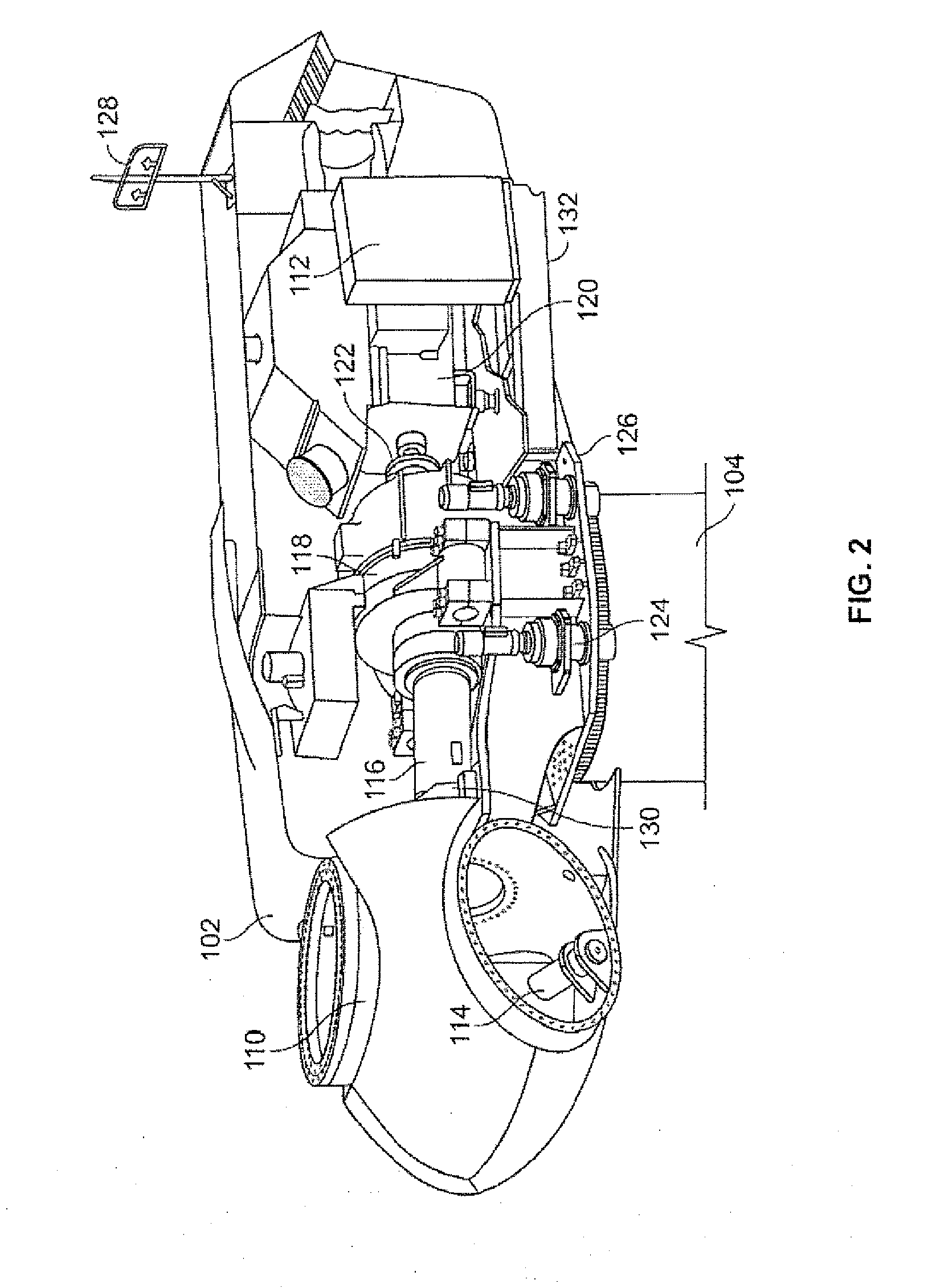
FIELD OF THE INVENTION[0001]The present invention is directed generally to wind turbines, and more particularly to a method for increasing energy capture and controlling blade pitch of a wind turbine blade.BACKGROUND OF THE INVENTION[0002]Recently, wind turbines have received increased attention as environmentally safe and relatively inexpensive alternative energy sources. With this growing interest, considerable efforts have been made to develop wind turbines that are reliable and efficient.[0003]Generally, a wind turbine includes a rotor having multiple blades. The rotor is mounted to a housing or nacelle, which is positioned on top of a truss or tubular tower. Utility grade wind turbines (i.e., wind turbines designed to provide electrical power to a utility grid) can have large rotors (e.g., 30 or more meters in length). In addition, the wind turbines are typically mounted on towers that are at least 60 meters in height. Blades on these rotors transform wind energy into a rotatio...

Claims


Application Information

Patent Timeline
Patent Type & Authority Applications(United States)
IPC IPC(8): F03D7/02
CPCF03D7/0224F03D7/043F05B2270/101Y02E10/723F05B2270/327F05B2270/336F05B2270/708F05B2270/32Y02E10/72
Inventor FRIC, THOMAS FRANKSTANDISH, KEVINPIERCE, KIRK GEELANDA, BERNARD
Owner GENERAL ELECTRIC CO
Learn More