
Method and apparatus for measuring enrichment of uf6

a technology of uranium hexafluoride and enrichment method, which is applied in the direction of material analysis using wave/particle radiation, x/gamma/cosmic radiation measurement, instruments, etc., can solve problems such as significant errors, and achieve low “sensitivity”, high “sensitivity”, and reduce the effect of errors

Inactive Publication Date: 2010-04-22
TRIAD NAT SECURITY LLC
View PDF3 Cites 9 Cited by
  • Summary
  • Abstract
  • Description
  • Claims
  • Application Information

AI Technical Summary

Benefits of technology

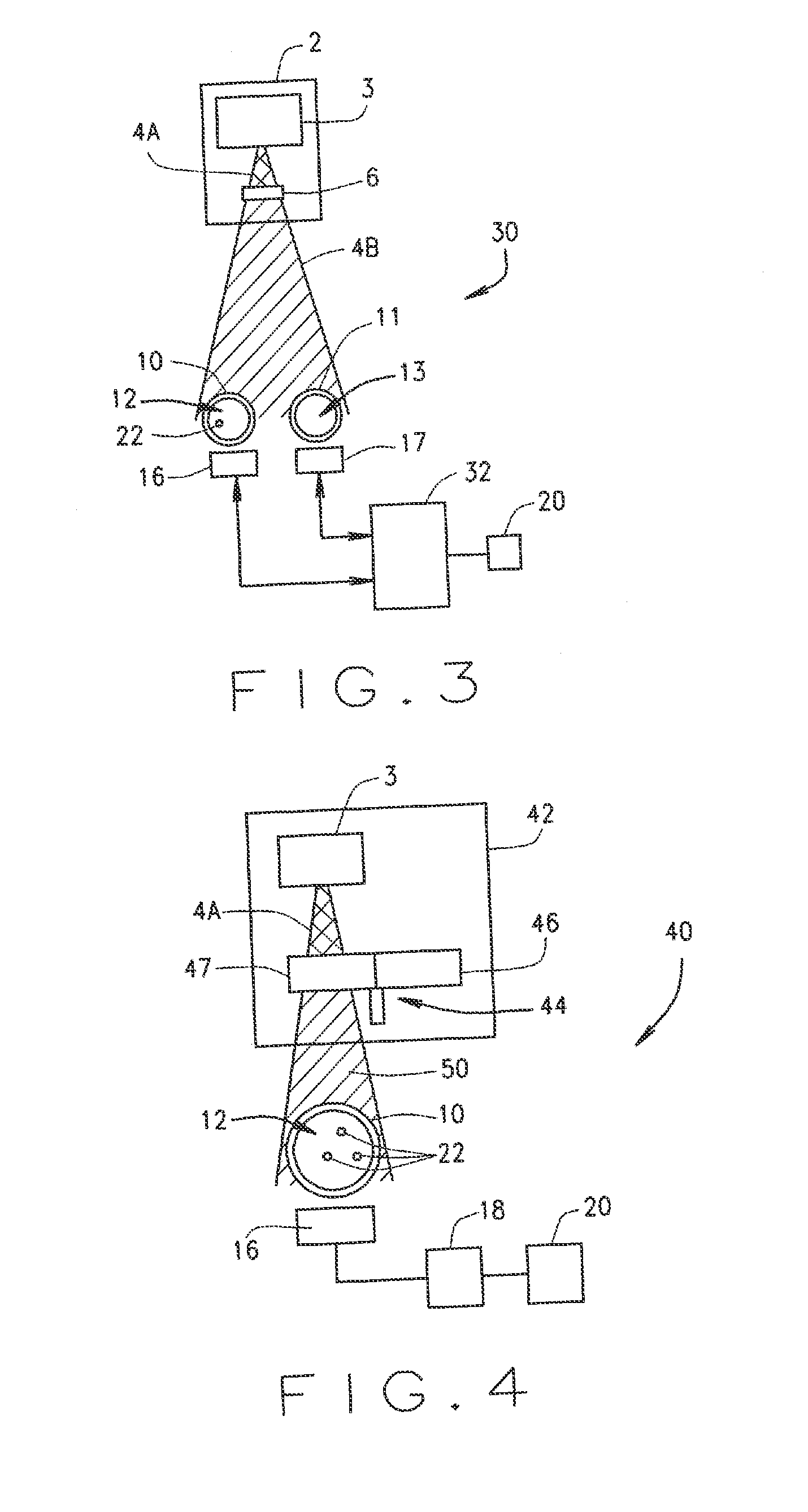
[0009]In a preferred embodiment, the calibration count is taken using a vacuum-containing second calibration test zone positioned adjacent to the UF6-containing first test zone such that the second test zone experiences substantially similar environmental conditions as does the first test zone. Thus, as the second test zone is substantially similar to the first test zone and experiences substantially similar environmental conditions as the first test zone, the number of X-rays it attenuates is substantially similar to the number of X-rays attenuated by the first test one absent a UF6 sample. Additionally, its location adjacent the first test zone allows for the X-ray beam to be directed at both test zones simultaneously, such that a second detector counts the X-rays passing through the second test zone while the first detector counts the X-rays passing through the first test zone and the UF6 sample.
[0010]In the alternative, a non-simultaneous count could be taken of the X-rays passing through the test zones, i.e. a count could be taken of the X-rays passing through only one of the test zones, and then a separate count could be taken of the X-rays passing through the other test zone. Thus, the calibration count could be taken simultaneously with, or before or after each run, or every N number of runs, which would reduce the error resulting from environmental changes between the time of calibration and the actual testing.
[0011]In another preferred embodiment, when placing a second, vacuum-containing test zone adjacent the UF6-containing test zone is not a viable option, a beam of X-rays is similarly directed at a UF6-containing test zone. However, this X-ray beam is filtered such that the X-rays in the beam have a first energy level for a period of time, and then a second energy for a period of time. This alternation of energy levels may be accomplished with two different filters mounted on a rotational assembly which rotates the filters such that the X-ray beam is alternately filtered by one and then the other. The first and second energy levels are selected such that either Uranium or the test zone container material has a high “sensitivity” to the change in energy levels while the other has a low “sensitivity” to the change. Thus, the attenuation caused by either the Uranium or the test zone container would be significantly different at the first energy level as the second, while the other material attenuates substantially the same amount of X-rays at both energy levels. This allows a differentiation between the X-rays attenuated by the container test zone and those attenuated by the UF6. Thus, this preferred embodiment allows for “re-calibration” when a sample is tested.
[0012]In another embodiment, the X-Ray beam is directed though the container test zone at an acute angle α to the longitudinal axis of the container test zone. This allows the X-rays more exposure to the UF6 gas, and more chance for the X-rays to be attenuated.
[0013]In another embodiment, the X-ray beam is again directed though the container test zone at an acute angle α to the longitudinal axis of the container test zone. However, the detector, which is preferably a phoswich scintillator is not positioned within the path of the X-ray beam, but is instead disposed along the pipe between the zones of entry and exit of the X-ray beam through the container test zone, and preferably rotated 90 degrees around the longitudinal axis of the test zone from the zones of entry and exit of the X-ray beam. This allows for fluorescent X-rays which are emitted by Uranium atoms when excited by X-rays to be detected by the detector while avoiding the Compton scattering and backscattering caused by the X-ray beam impinging the container walls. The count rate of the fluorescent X-rays emitted by the Uranium can then be used, in combination with the count of 186 keV gamma rays emitted spontaneously by the 235U in the sample to determine the enrichment of the 235U in the sample.

Problems solved by technology

However, geometry, aging or temperature changes between the test zones on which the calibrations were taken and those actually used with the experiments cause significant error.

Method used


Image

  • Method and apparatus for measuring enrichment of uf6
  • Method and apparatus for measuring enrichment of uf6
  • Method and apparatus for measuring enrichment of uf6

Examples


Embodiment Construction

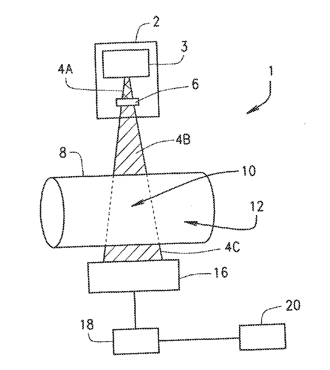
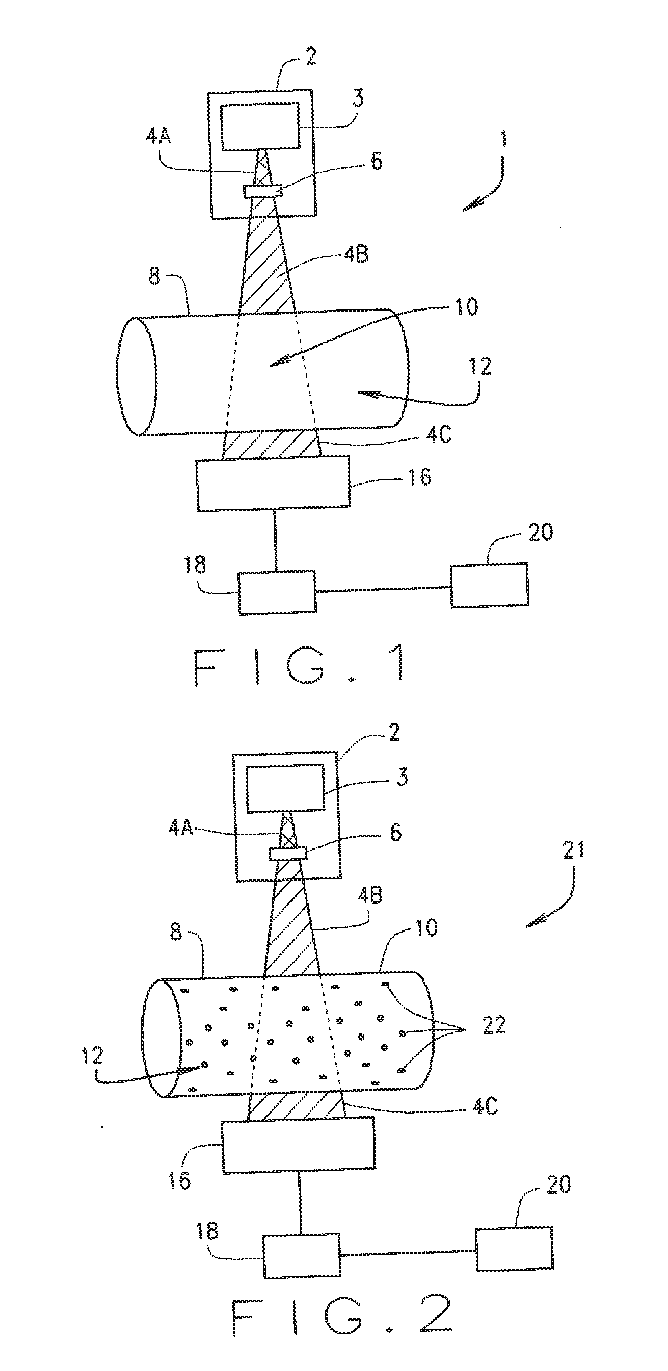
[0022]FIG. 1 illustrates a schematic diagram of an embodiment of a system 1 for determining the enrichment factor of 235U in Uranium Hexafluoride (UF6). An artificial X-ray source 2, which is preferably a 130 kV X-ray source and which can preferably artificially produce and emit X-rays from about 12 keV to about 120 keV, includes an X-ray generation source 3 which emits a collimated beam of X-rays 4, and an X-ray filter 6. The X-ray generator source 3 is a man-made machine which artificially produces X-rays preferably utilizing an energetic electron process. The X-ray generation source 3 generates and emits X-ray radiation as an X-ray beam 4. X-ray beam 4 is divided into several different sections, which are shown as three in number and are labeled 4A, 4B and 4C, each of which designate a portion of X-ray beam 4 with a specific intensity and / or energy level. For example, as X-ray beam 4 is emitted from the X-ray generator source 3, it is labeled X-ray beam 4A. In the illustrated str...


PUM


Abstract

A system and method are disclosed for determining the enrichment of 235U in Uranium Hexafluoride (UF6) utilizing synthesized X-rays which are directed at a container test zone containing a sample of UF6. A detector placed behind the container test zone then detects and counts the X-rays which pass through the container and the UF6. In order to determine the portion of the attenuation due to the UF6 gas alone, this count rate may then be compared to a calibration count rate of X-rays passing through a calibration test zone which contains a vacuum, the test zone having experienced substantially similar environmental conditions as the actual test zone. Alternatively, X-rays of two differing energy levels may be alternately directed at the container, where either the container or the UF6 has a high sensitivity to the difference in the energy levels, and the other having a low sensitivity.

Description

STATEMENT OF FEDERAL RIGHTS[0001]The United States government has rights in this invention pursuant to Contract No. DE-AC52-06NA25396 between the United States Department of Energy and Los Alamos National Security, LLC for the operation of Los Alamos National Laboratory.FIELD OF THE INVENTION[0002]The present invention relates to systems and methods for measuring enrichment of Uranium Hexafluoride (UF6). More specifically, the present invention relates to a system and method for directing ionizing radiation in the form of X-Rays at a radiation pervious chamber containing UF6 to determine the amount of 235U present relative to the amount of Uranium.BACKGROUND ART[0003]It has been reported that approximately 99.99% of all natural Uranium on Earth is composed of either 235U or 238U, with 238U comprising 99.28% and 235U comprising 0.71% of all natural Uranium. However, in order to achieve a nuclear chain reaction capable of sustaining a fission reaction in Uranium, a majority of the neu...

Claims


Application Information

Patent Timeline
IPC IPC(8): G01T1/36G01N23/06G01N23/223
CPCG01N23/223G01N2223/076G01T1/167G01T1/2008
Inventor HILL, THOMAS ROYIANAKIEV, KIRIL DIMITROV
Owner TRIAD NAT SECURITY LLC
Learn More