
Apparatus comprising frequency selective circuit and method

a frequency selective circuit and receiver technology, applied in the direction of filters, code conversion, instruments, etc., can solve the problems of increasing design complexity and design time, affecting the performance of known frequency translating delta sigma modulators, and far from the requirements of radio receivers of modern telecommunication systems, so as to achieve good frequency selectivity and reduce noise significantly , the effect of reducing the sensitivity to 1/f-nois

Active Publication Date: 2010-04-22
WSOU INVESTMENTS LLC
View PDF11 Cites 23 Cited by
  • Summary
  • Abstract
  • Description
  • Claims
  • Application Information

AI Technical Summary

Benefits of technology

[0018]In an embodiment, the impedance circuits provide good frequency selectivity at radio frequencies. Therefore greater amplification can be applied at an earlier stage than in traditional receiver architectures, which results in better noise performance and significantly reduced sensitivity to 1 / f-noise. Because impedance circuits are used within a feedback loop, many nonidealities are reduced by a feedback mechanism.

Problems solved by technology

This consumes silicon area and increases design complexity and design time.
Known problems in A / D converters are related to linearity and so called 1 / f-noise.
However, the performance of known frequency translating delta sigma modulators is far from the requirements of radio receivers of modern telecommunication systems.
Second, an unfiltered 1-bit bitstream feedback signal contains high spectral energy at frequencies that may become mixed with the desired signal band in up conversion.
Therefore, resolution in prior art modulators is most likely limited by nonidealities in feedback D / A-conversion and / or in the frequency up conversion.
All nonlinearities in the feedback path will further degrade the modulator performance.

Method used


Image

  • Apparatus comprising frequency selective circuit and method
  • Apparatus comprising frequency selective circuit and method
  • Apparatus comprising frequency selective circuit and method

Examples


Embodiment Construction

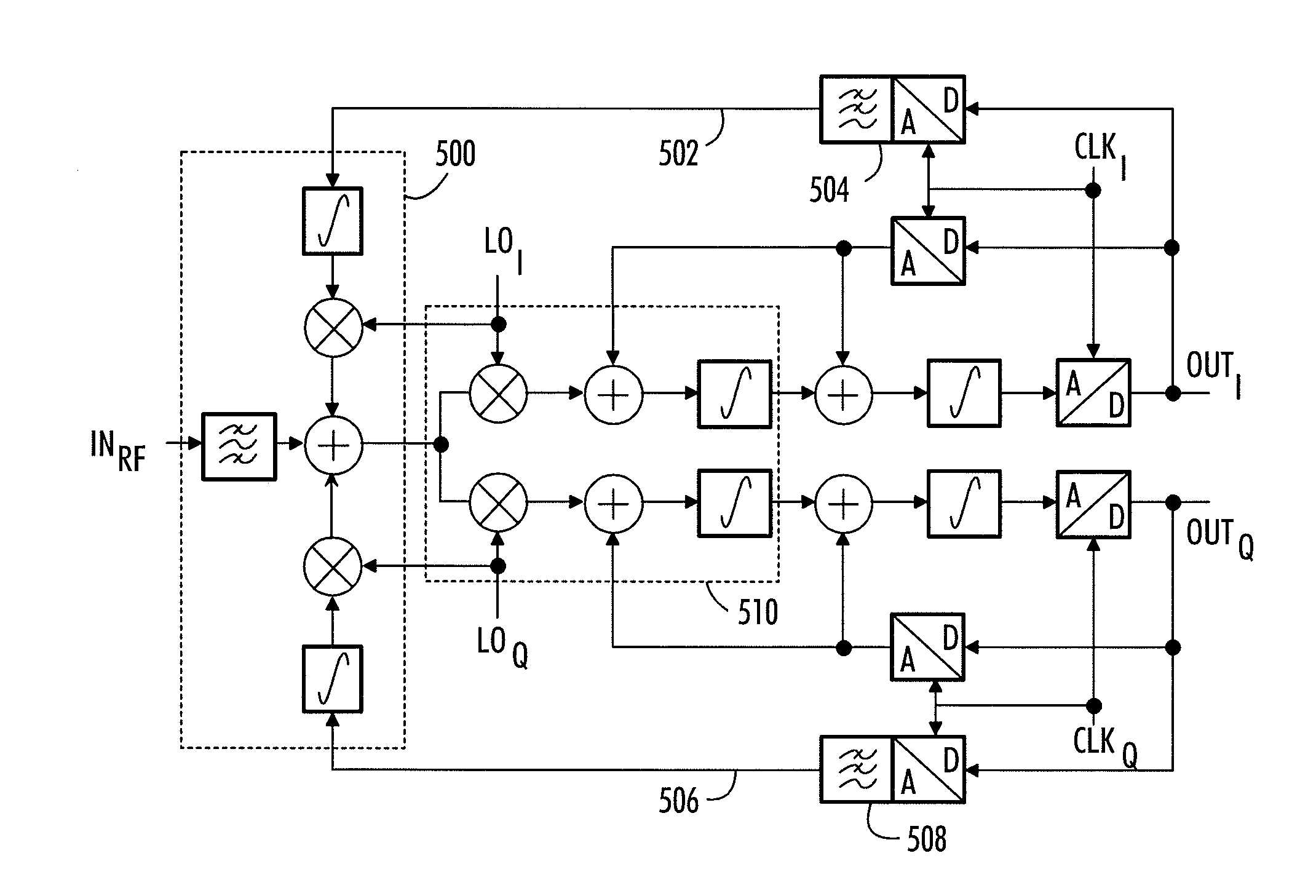
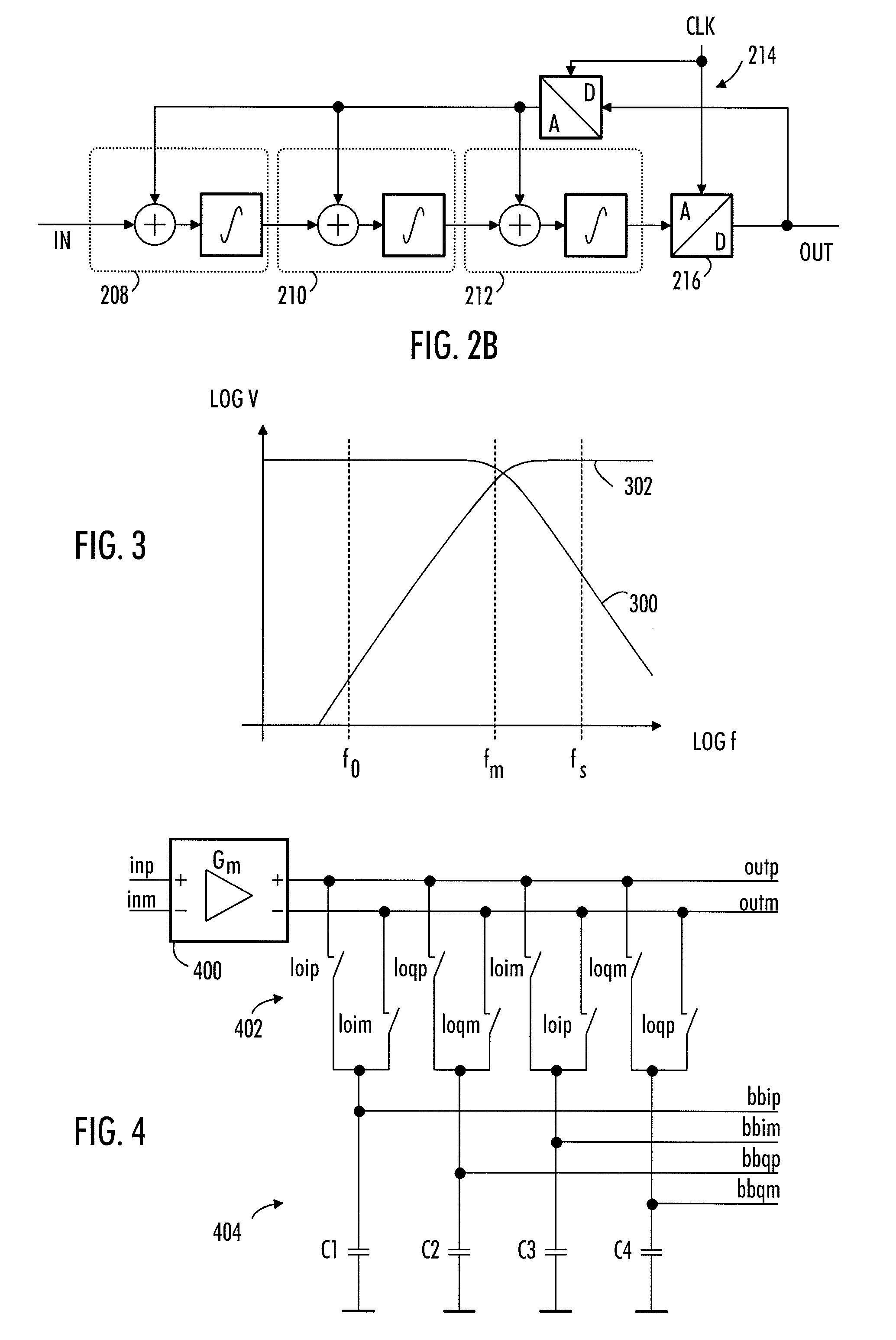
[0038]With reference to FIGS. 1A, 1B, 1C and 1D, examine examples of a receiver to which embodiments of the invention can be applied. The receiver of FIG. 1A comprises an antenna 100 receiving a signal. The antenna 100 is connected to a filter 102 configured to filter undesired frequencies from the received signal. The filtered signal is taken to a low noise amplifier 104 configured to amplify the signal. The amplified signal is taken to a sigma delta modulator 106 configured to convert the amplified analog signal to a digital form. At the output of the sigma delta modulator the received signal is in a digital form. In this example the digital signal is split into inphase and quadrature phase components. The receiver of FIG. 1A is a direct conversion receiver (also known as zero-IF receiver) where the signal at the input of the sigma delta modulator is an RF signal.

[0039]FIG. 1B illustrates a superheterodyne receiver comprising a mixer 108 mixes the received signal with a local osci...


PUM


Abstract

An apparatus, having as an input an analog signal, is provided. The apparatus comprises a first circuit comprising an impedance transferring circuit configured to band pass filter the input signal, obtaining a filtered signal; the impedance transferring circuit comprising: a transconductance amplifier (1102), and a switching arrangement (1106, 1108) and an impedance circuit (404) connected in series, the switching arrangement being configured to switch the impedance of the impedance circuit of the impedance transferring circuit from base band to the frequency of the input signal. The apparatus further comprises a second circuit (1112) configured to perform down mixing to the filtered signal obtaining a base band signal and a feedback loop connecting the base band signal to the switching arrangement (1114, 1116) and the impedance circuit, the signal of the feedback loop configured to control the properties of the first circuit.

Description

FIELD [0001]The invention relates to an apparatus comprising a frequency selective circuit and a receiver comprising such an apparatus.BACKGROUND [0002]Digital signal processing is becoming more and more important in telecommunication apparatuses. This applies especially to wireless telecommunication. A signal is processed digitally in a transmitter, converted to an analog form and transmitted wirelessly to a receiver, which converts the signal back to a digital form.[0003]In recent years, several different wireless telecommunications standards have emerged. These standards support systems based on GSM, CDMA and WCDMA techniques, for example. From the user's point of view, a transceiver supporting several standards provides most versatile usability. Therefore, transceivers capable of communication in systems based on different technologies have been developed.[0004]In implementing a radio receiver supporting several radio standards, analog base band filtering and A / D-conversion band...

Claims


Application Information

Patent Timeline
Patent Type & Authority Applications(United States)
IPC IPC(8): H03M1/12
CPCH03H15/00H03H19/008H03M3/438H03M3/40H03M3/404H04B1/18
Inventor KOLI, KIMMO
Owner WSOU INVESTMENTS LLC
Learn More