System and method for creating a proximity map of living beings and objects

a technology of living beings and objects, applied in the field of tracking and notification systems, can solve the problems of slow process, patients with these symptoms, and the method is determined impossible, and achieve the effect of improving the accuracy and accuracy of the proximity map

Active Publication Date: 2010-04-22
WONG CHON MENG
View PDF65 Cites 24 Cited by
  • Summary
  • Abstract
  • Description
  • Claims
  • Application Information

AI Technical Summary

Benefits of technology

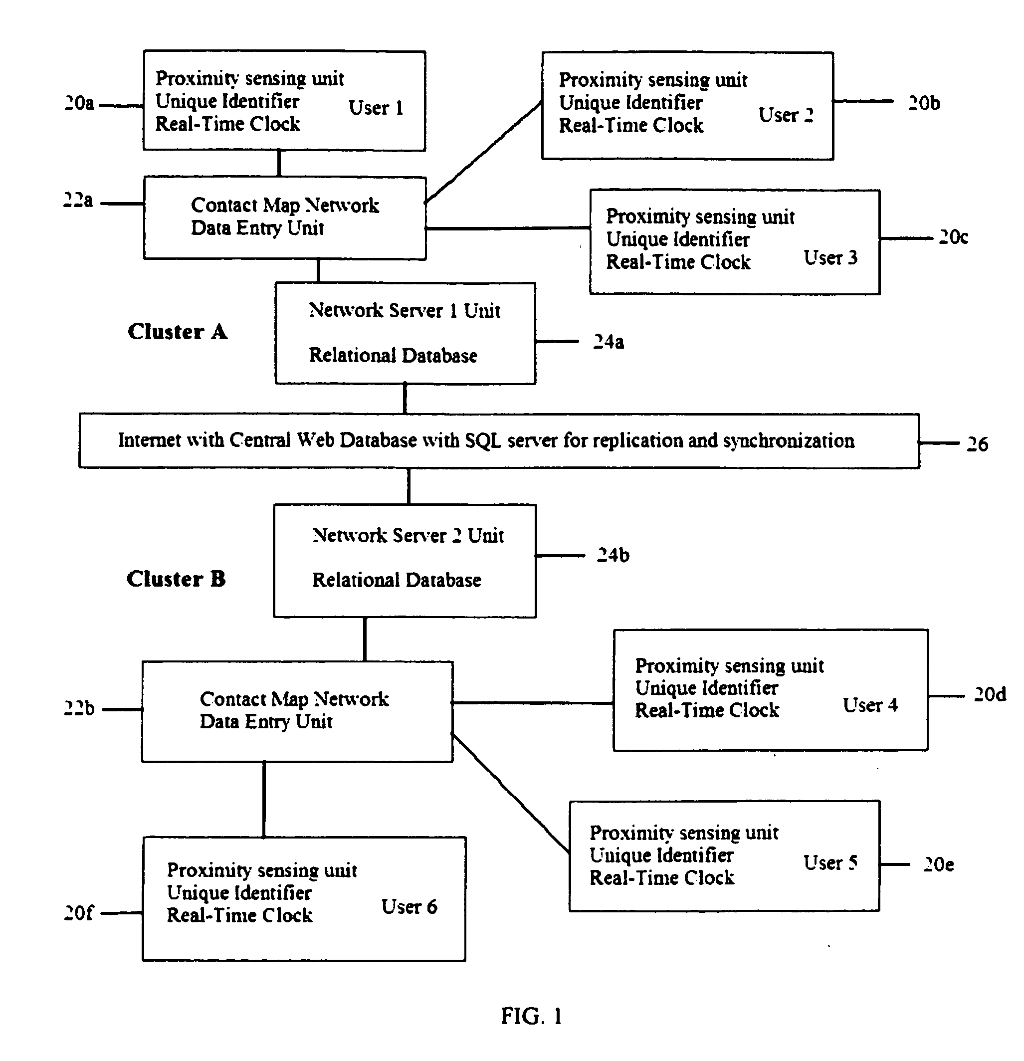
[0013]Everyone within the population uses a contact or proximity-sensing device with a unique identifier. All units that come in contact will record this unique identifier. Each device unit will have a list of which it has encountered and how distant are these contacts. Each record has an associated time stamp. A detail triangulation map of contacts can then be constructed. A contact network map consisting of description of location of each individual with a time stamp is generated and stored as a record in the relational database. A distributed network map entry system collects all maps from each individual in its contact neighborhood. All movements are expressed as a moving network mesh of triangles with time stamp, which in turn can be represented as time dependent matrices. The local database resides on a local network server and constantly updated. The contact network map is made complete through exchange of network maps from other server locations through the Internet using a central web database. The database is replicated and synchronized allowing every local server capable of generating reports during analysis. An algorithm using the matrix elements and time sliced iteration procedure can list the people in contact under specific criteria accurately from the database.

Problems solved by technology

The blood sample testing of hospital population including visitors is an accurate method but is a very slow process since blood sampling takes time and its analysis also take significant amount of time before a determination can be made.
If the hospital population is large, this method is determined impossible.
However, not all SARs patients have these symptoms at the start of infection.
Quarantine everyone working in the infected area does not account for those who are infected due to unscheduled visitors.
However, there is no proximity map or method to trace all the events that carcasses are close to each other during the meat packing process.

Method used


Image

  • System and method for creating a proximity map of living beings and objects
  • System and method for creating a proximity map of living beings and objects
  • System and method for creating a proximity map of living beings and objects

Examples


case 1 (

Case 1 (Location by Distance Measurements Between Two “H” Units)

[0085]In FIG. 7, there are two or more high radio frequency power “H” units with enough power transmission for coverage over the entire building. The rest of the units “R”, “S” and “T” are the normal power units of proximity sensing systems. The high power unit is achieved by using a network server unit and adds RF power amplifiers to their transceivers, 66, in FIG. 4. These units must be located at a known fixed location or it has a precision GPS locator to give its actual position. One “H” unit is capable of communicating with at least another “H” unit. In addition, the two communicating “H1”, 120, and “H2”, 122, units (See FIG. 7) have to synchronize and coordinate such that both would not transmit at the same time. This is achieved by sending each other a prior to transmit notification signal, informing others that it will transmit in the next x milliseconds. All units receiving this signal, including the “H” unit, ...

case 2 (

Case 2 (Location Determination from One Distance Measurement from One “H” Unit)

[0087]In the scenario when only one “H” unit location is available, Unit “S”126, can infer its location if it triangulates with unit “H1”, 120, and another unit “T”, 128, with sides L4, 136, L5, 138 and L6, 140. However, the absolute location of unit “T”, 128, would not be known until it has determined its absolute location from the two H units using the triangle with sides L1, 130, L5, 138, and L7, 142.

case 3 (

Case 3 (Location Determination from Other Non “H” Units)

[0088]FIG. 8 shows that the mobile “U”, 148, unit's location determination is to derive from two other non “H” units. FIG. 8 shows three mobile units, “R”, 146, “T”, 150, and “U”, 148, where units “R”, 146, and “T”, 150, positions were previously determined from their triangulation described in Case 1 (FIG. 7). However, this assumes the units “R”, 146, and “T”, 150, locations were determined within a very short time before “U”, 148, position is found. This is a quasi-static assumption.

[0089]By induction, the above steps can be repeated to determine all locations for any number of mobile units as long as they satisfy any one of the above cases under the quasi-static assumption.

7) Matrix Formulation of the Contact Tree Network Map

[0090]The overall contact network map can be represented in a matrix format. All the unique identifiers form a vector as illustrated by equation 2 as [RSTU].

[0091]The contact tracking network tree is for...


PUM


Abstract

A contact or proximity network map defines who and what objects have come in contact of each other including location and time. This map selects the list people who have come in contact with known infected people based on contagious disease epidemiology criteria for the purpose of control its spread, or to prevent radiation poisoning, limit bio-chemicals exposure, etc. This selected list of people then undergoes testing and quarantine procedures. It can monitor hygiene practices and reduce nosocomial infections in hospitals and mitigate the pandemic flu threat by controlling spread and control contamination. It controls people interaction, information flow in a high security environment, control crime or gang activities. Each person or object has a proximity-sensing device with unique ID, which is recorded by the encountered units during contact. This information is stored with time stamp in a relational database. It generates contact maps with real time replication of its database via a central web database for retrieval and analysis at any site.

Description

CLAIM OF PRIORITY[0001]This application claims priority under 35 U.S.C. 119(e) to U.S. Provisional Application No. 60 / 657,485, filed on Mar. 1, 2005, the entire contents of which are hereby incorporated by reference.BACKGROUND OF INVENTION[0002]This invention relates to the general method of tracking and notification system for the purpose of tracking of movement of people or objects in close proximity. The importance is that if an event is to be traced because of close contact, this system provides an efficient method of actually identifying the people or objects that are within this network during any given period so that testing and quarantine procedures can do done accurately and precisely.[0003]For example, in a hospital environment, if there is a contagious disease outbreak and each patient, it is required to identify the people exposed to the infectious agent within a certain distance. If all visitors and staff in the hospital are tagged with proximity detection and identific...

Claims


Application Information

Patent Timeline
Patent Type & Authority Applications(United States)
IPC IPC(8): G08B1/08G06F15/173
CPCG01S5/0284G01S13/74G01S5/14
Inventor WONG, CHON MENG
Owner WONG CHON MENG
Why Eureka
Try Eureka