Blow molding device
- Summary
- Abstract
- Description
- Claims
- Application Information
AI Technical Summary
Benefits of technology
Problems solved by technology
Method used
Image
Examples
first embodiment
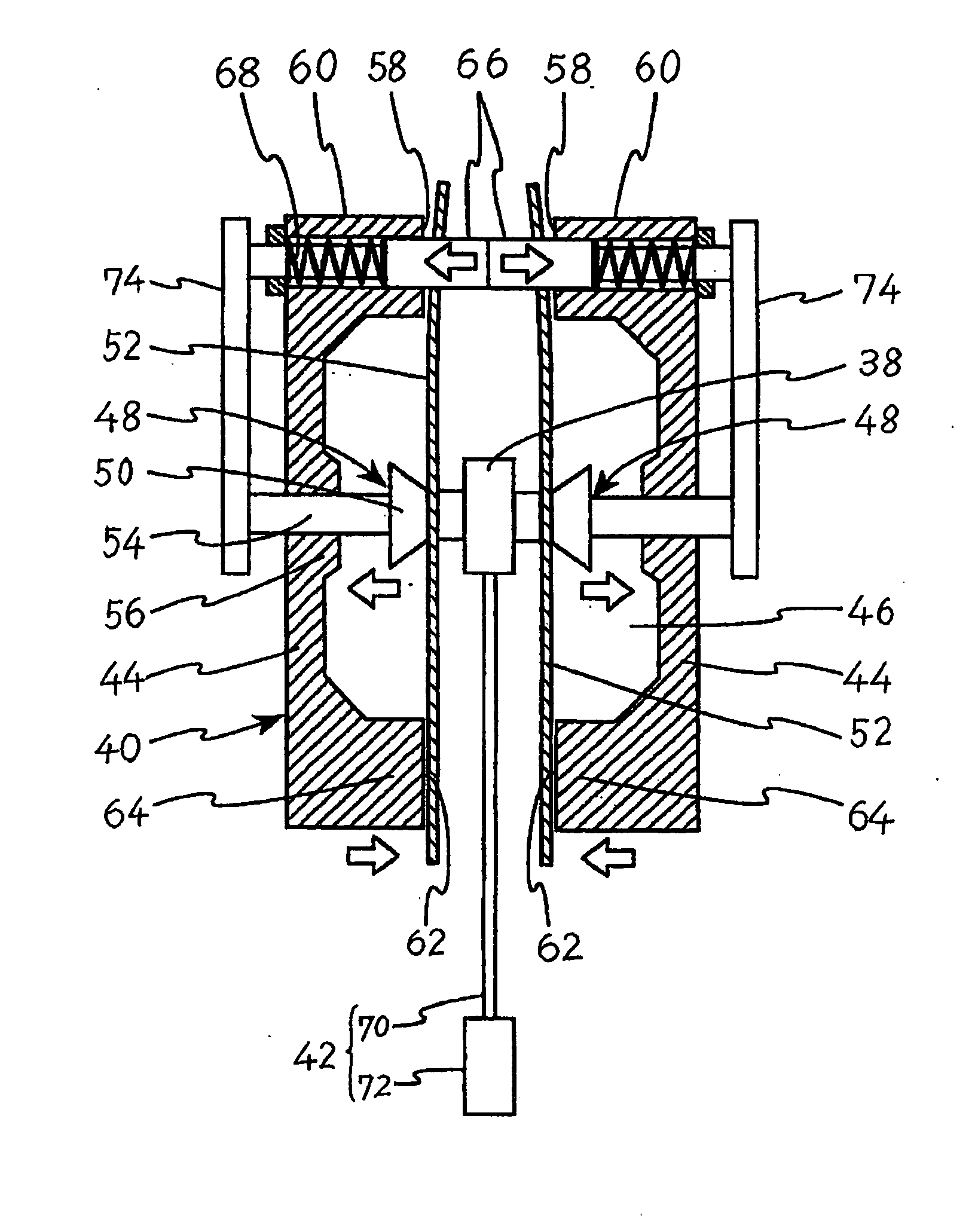
[0078]As shown in FIG. 11, in the first embodiment, the drive control pins 66 are provided in the upper part 60 of the blow mold 40 so as to contact each other. Therefore, the moving speed of the blow mold 40 is equal to that of the drive control-pins 66, and since the slide cores 48 are linked to the drive control pins 66 via the linking members 74, the retreating speed of the slide cores 48 can be made equal to the moving speed of the blow mold 40.
second embodiment
[0079]Next, the present invention will be explained with reference to FIG. 12.
[0080]A blow mold 76 used in the second embodiment is provided with drive control pins 78 in mold members 80 in an upper part of the blow mold 76. The drive control pins 78 do not contact each other, but are arranged such that when the blow mold 76 is closed, a tip end of each of the drive control pins 78 contacts an upper mating face 84 of a facing mold member 80. And the tip end of each of the drive control pins 78 contacts the upper mating face 84 of the facing mold member 80 simultaneously with the holding of a parison and a built-in part with a slide core 86. Therefore, the tip end of each of the drive control pins 78 securely contacts the upper mating face 84 of the facing mold member 82, while the slide core 86 can retreat while holding the parison and the built-in part by virtue of the drive control pins 78.
[0081]In this case, the mold members 80 approach each other at the same speed, and consequen...
third embodiment
[0083]Next, the present invention will be explained with reference to FIG. 13.
[0084]A blow mold 96 used in the third embodiment is provided with drive control pins 98 in upper parts 100 of mold members 102. The drive control pins 98 do not contact each other, but are arranged such that when the blow mold 96 is closed, a tip end of each of the drive control pins 98 contact an upper mating face 104 of a facing mold member 102, similarly to the second embodiment.
[0085]Therefore, in the present embodiment, in order to reduce the sliding speed and the sliding distance of a slide core 106 to half of those of the drive control pin 98, a linking member driving gear 108 is provided in the vicinity of a back end of the drive control pin 98. The linking member driving gear 108 includes a larger gear and a smaller gear provided on the same axis in close contact with each other. The number of teeth of the larger gear is determined twice as large as that of the smaller gear.
[0086]A gear is provid...
PUM
 Abstract
Description
Claims
Application Information
 - R&D
- Intellectual Property
- Life Sciences
- Materials
- Tech Scout
- Unparalleled Data Quality
- Higher Quality Content
- 60% Fewer Hallucinations
Browse by: Latest US Patents, China's latest patents, Technical Efficacy Thesaurus, Application Domain, Technology Topic, Popular Technical Reports.
© 2025 PatSnap. All rights reserved.Legal|Privacy policy|Modern Slavery Act Transparency Statement|Sitemap|About US| Contact US: help@patsnap.com


