
Membrane for an electroacoustic transducer and acoustic device

a technology of electroacoustic transducers and membranes, applied in the direction of electrical transducers, transducer diaphragms, instruments, etc., can solve the problems of weak audio performance of known acoustic devices, and achieve the effect of proper audio performance and quality, and efficient air volume shift over an entire duty cycl

Inactive Publication Date: 2010-04-15
KNOWLES ELECTRONICS ASIA
View PDF4 Cites 10 Cited by
  • Summary
  • Abstract
  • Description
  • Claims
  • Application Information

AI Technical Summary

Benefits of technology

[0020]When a transducing element (e.g. a coil attached to the membrane being in a magnetic field) excites the membrane (i.e. the rigid and the flexible parts in common), the rigid part is moved in a manner to essentially maintain its shape (i.e. translatory moved), whereas the value of the curvature of the flexible portion is changed, so that both the rigid and the flexible portion of the membrane contribute to a volume of a shifted air. Therefore, it is possible to increase the sound pressure level (SPL) and thus improve the performance of an acoustic device significantly. This is particularly advantageous for the design of small dimensioned acoustic devices, for instance for loudspeakers of mobile phones. Such small dimensioned acoustic devices usually suffer from a non-sufficient loudness. Because according to the invention also the flexible portion contributes to the moved air volume, it is possible to obtain a higher sound pressure with the same size of the membrane. Alternatively, the same sound pressure can be obtained with a smaller size of the membrane. This allows to manufacture miniaturized acoustic devices.
[0023]The rigid membrane portion may be essentially planar. Therefore, the rigid membrane portion may function in a similar manner as a piston shifting a large amount of air in an upward direction. Furthermore, a planar surface is easy to manufacture so that the membrane may be, in its entirety, easy to manufacture. Beyond this, a planar geometry may allow to manufacture the membrane in a flat and space-saving manner. Thus, the manufacture of flat loudspeakers with proper audio performance is possible. Alternatively, the rigid portion may have any other desired shape, like a bent or curved shape.
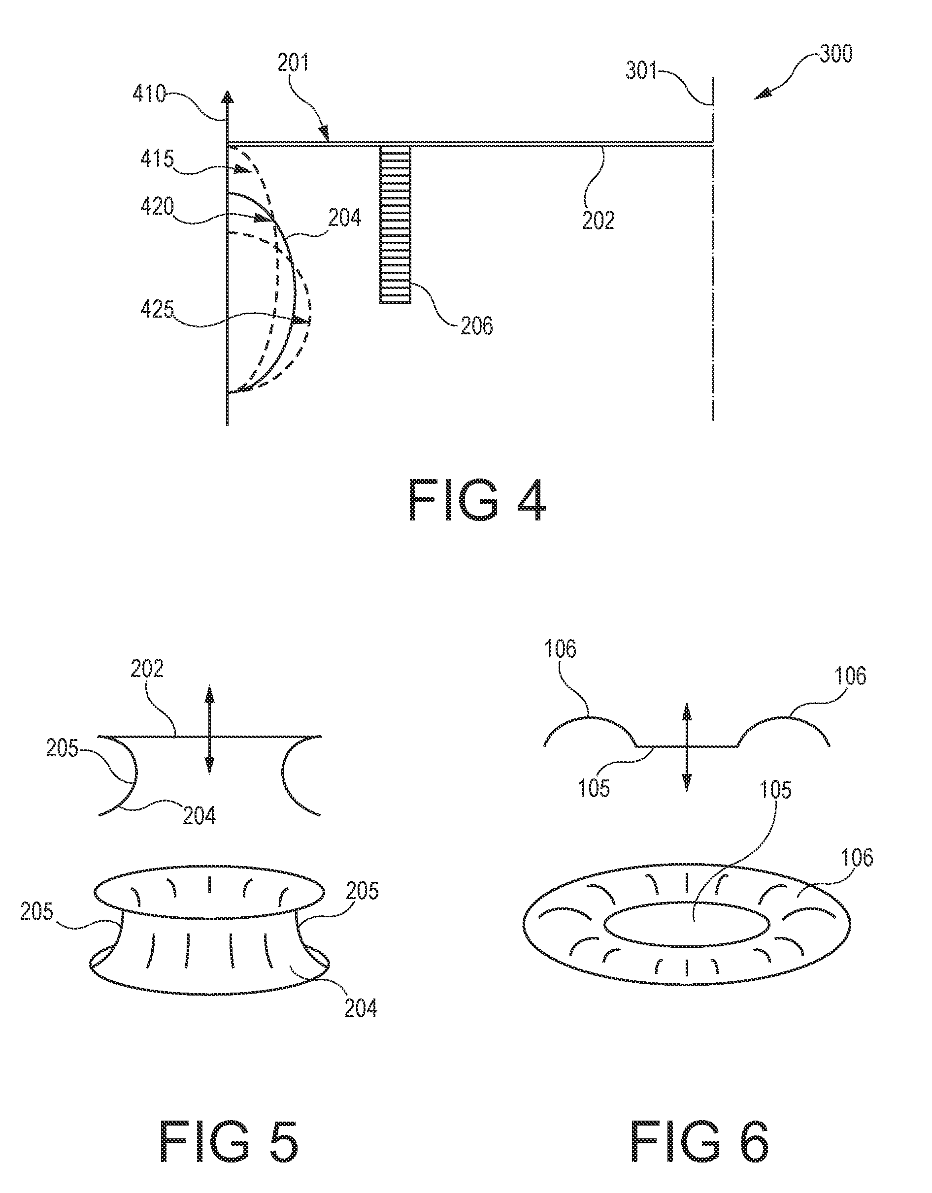
[0024]The flexible membrane portion may be essentially wheel-rim shaped. Such a wheel-rim is shown, for instance, in FIG. 5. “Wheel-rim shaped” denotes the shape of a deformed cylinder in which the curved surface of the cylinder is arced, or an indentation, particularly with an elliptic shape, is formed into the curved portion. Such a configuration is mechanically stable, easy to manufacture and contributes significantly to the shifted air volume, thereby achieving a proper performance of the loudspeaker.
[0027]It is advantageous if an exterior surface of the flexible membrane portion has, in a lower dead point of the membrane (that is to say when the flexible membrane portion is compressed to a maximum extent), a semi-circular curvature. A lower dead point is a reversion point in which the membrane motion changes from a downward motion to an upward motion. When the lower dead point of the membrane coincides with a semi-circular shape of the flexible membrane portion, an efficient air volume shift over an entire duty cycle is obtained. When the rigid membrane portion moves beyond said optimum lower dead point the smaller half axis becomes the longer half axis, which is then essentially normal to the motion direction of the loudspeaker. In this state, no additional sound is generated. Even worse, the loudspeaker becomes more quiet since the air stream caused by the flexible membrane portion changes its direction.
[0028]The membrane may further be adapted in such a manner that a total harmonic distortion of the flexible membrane portion is essentially compensated by a total harmonic distortion of the rigid membrane portion. In some cases, the membrane is designed such that the total THD is as small as possible. Since the THD of the flexible membrane portion is, in a rough approximation, independent of THD which is generated by the motion of the rigid portion of the membrane, the THD of the rigid portion can (partially or entirely) be compensated by the THD of the flexible portion. Accordingly, the total THD (of the entire membrane) can be made as small as possible. For this reason, the length of the semi-major axis is adjusted accordingly. In this case, it may also be advantageous if the membrane moves beyond the lower dead centre given by the half circle shape of the flexible membrane portion. Therefore, exemplary embodiments of the invention may allow to obtain more SPL with smaller loudspeakers, and / or a compensation of THD. Such advantages may be particularly obtained in loudspeakers or receivers. For such embodiments, the materials of membrane, the thickness of the membrane portions, and the geometric shapes of the membrane portions are adjusted accordingly. This allows to obtain a loudspeaker with a proper audio performance and quality.

Problems solved by technology

Nevertheless, the loudspeakers and / or microphones must provide a sufficient sound pressure respectively a sufficient sensitivity what is a challenging task for the designers of such electro-acoustic transducers.
However, known acoustic devices suffer from a weak audio performance, particularly when the acoustic devices are small in size.

Method used


Image

  • Membrane for an electroacoustic transducer and acoustic device
  • Membrane for an electroacoustic transducer and acoustic device
  • Membrane for an electroacoustic transducer and acoustic device

Examples


Embodiment Construction

[0038]The illustration in the drawing is schematically. In different drawings, similar or identical elements are provided with the same reference signs.

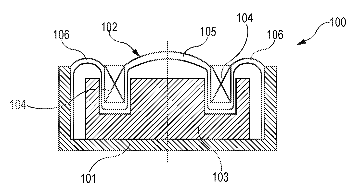
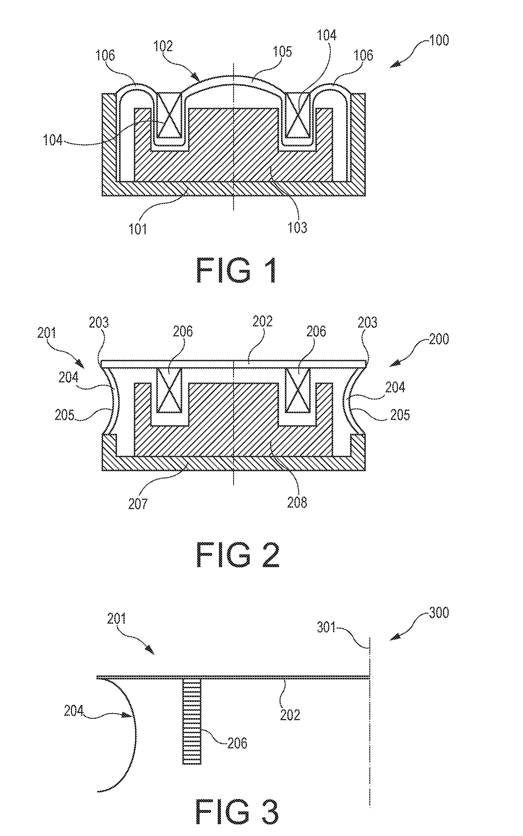
[0039]FIG. 1 shows a conventional speaker 100 (e.g. for mobile phones) comprising a housing 101, a membrane 102, a magnet 103 and a coil 104. The membrane 102 comprises a rigid portion 105 which moves piston-like and a spring portion 106 which through its deformation allows a movement of the rigid portion 105.

[0040]FIG. 2 shows a speaker 200 according to an embodiment of the invention. The loudspeaker 200 comprises a compound membrane 201 formed by two layers. These layers can be made of thermoplastic materials, for instance. However, also a single layer configuration of the membrane 201 is possible. Furthermore, FIG. 2 shows a housing or base member 207 and a magnetic arrangement 208. The base element 207 (which may also be denoted as a basket) may be made of any appropriate material, like metal or plastics, for instance polycarbona...


PUM


Abstract

A membrane for an electroacoustic transducer is disclosed, wherein said membrane (201) comprises a rigid membrane portion (202) having an edge (203); a flexible membrane portion (204) being connected to the rigid membrane portion (202) along the edge (203); wherein an exterior surface (205) of the flexible membrane portion (204) is concave in an idle state of the membrane (201) and shaped such that a change of the curvature of said exterior surface (205) contributes to an air volume shifted by the rigid membrane portion (202) when membrane (201) is excited.

Description

FIELD OF THE INVENTION[0001]The invention relates to a membrane for an electroacoustic transducer and to an acoustic device comprising such a membrane.BACKGROUND OF THE INVENTION[0002]Because of the ever decreasing size of consumer electronics, loudspeakers and / or microphones have to become smaller as well. Nevertheless, the loudspeakers and / or microphones must provide a sufficient sound pressure respectively a sufficient sensitivity what is a challenging task for the designers of such electro-acoustic transducers.[0003]For the acoustical performance of a speaker, the sound pressure level (SPL) is an important parameter which usually should be as high as possible. In conventional dynamic speakers (see FIG. 1 and FIG. 6), a membrane displaces air and thus produces sound. It comprises two parts, one is relatively compliant and allows the movements of the membrane, the other is rather stiff to effectively displace air. The SPL is given by the displaced air volume, i.e. the displaced ar...

Claims


Application Information

Patent Timeline
IPC IPC(8): H04R25/00H04R7/00
CPCH04R7/20H04R2499/11H04R2307/207
Inventor WINDISCHBERGER, SUSANNELUTZ, JOSEF
Owner KNOWLES ELECTRONICS ASIA
Learn More