Impulse immunity test apparatus

a test apparatus and impulsive immunity technology, applied in the direction of resistance/reactance/impedence, marginal circuit testing, instruments, etc., can solve the problem of inability to clearly determine the level of voltage actually applied to an electronic circuit, the peak value of noise input to an electronic circuit is not clear, and the error cannot be specified

Inactive Publication Date: 2010-04-15
RENESAS ELECTRONICS CORP +2
View PDF2 Cites 6 Cited by
  • Summary
  • Abstract
  • Description
  • Claims
  • Application Information

AI Technical Summary

Benefits of technology

[0008]The present invention provides an impulse immunity test apparatus capable of applying a rectangular wave in the positive and negative directions, irrespective of types of lines, such as a power source line, a ground line, and a signal line, to test an immunity of an electronic circuit.

Problems solved by technology

The aforementioned application methods in the related art have a problem that they cannot clearly determine a level of a voltage actually applied to an electronic circuit.
Therefore, there is a problem that a peak value of noise inputted to an electronic circuit is not clear.
Additionally, there is another problem that the direction of a noise, i.e., the positive direction or the negative direction, that caused an error cannot be specified.

Method used


Image

  • Impulse immunity test apparatus
  • Impulse immunity test apparatus
  • Impulse immunity test apparatus

Examples


examples

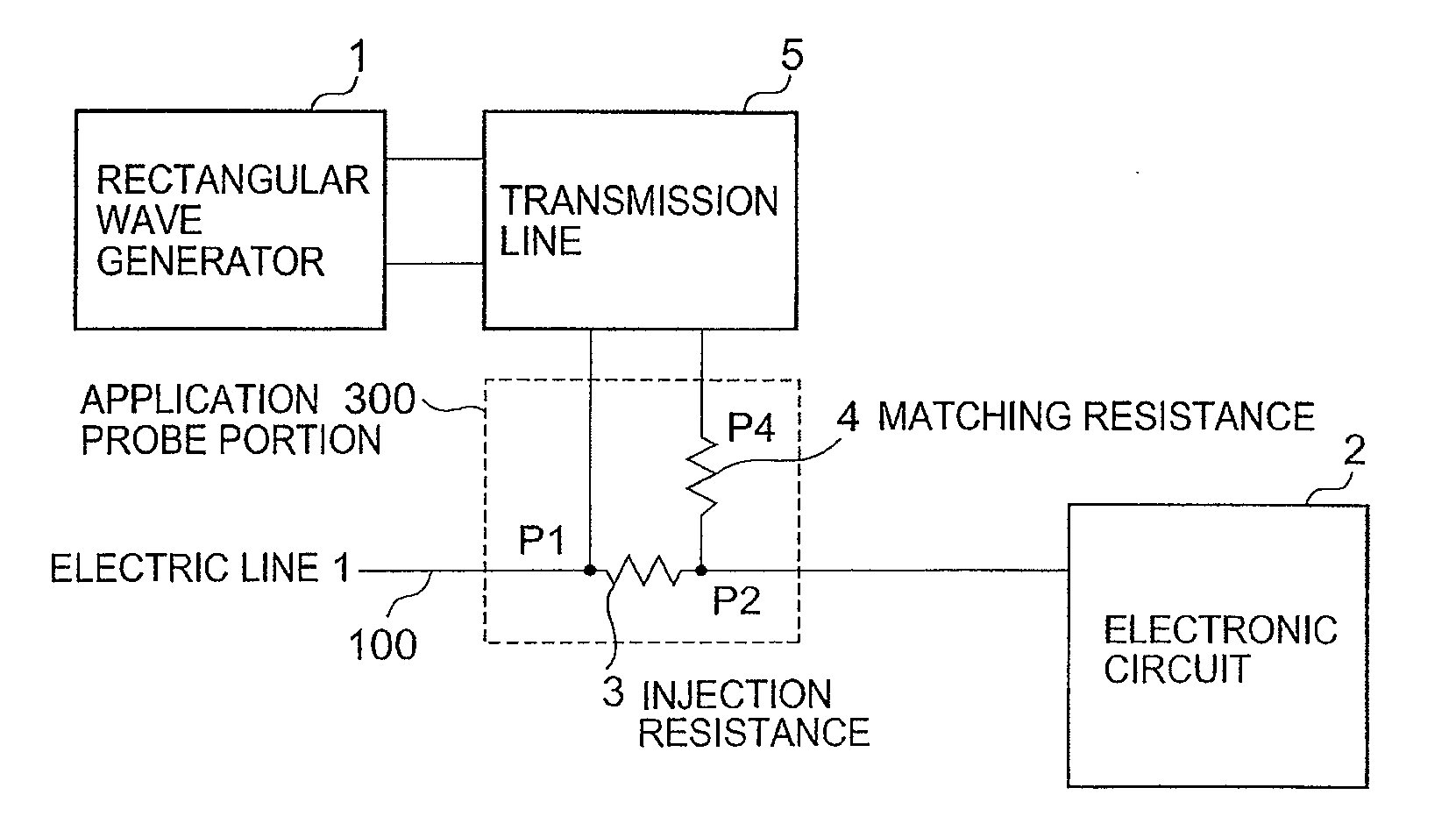
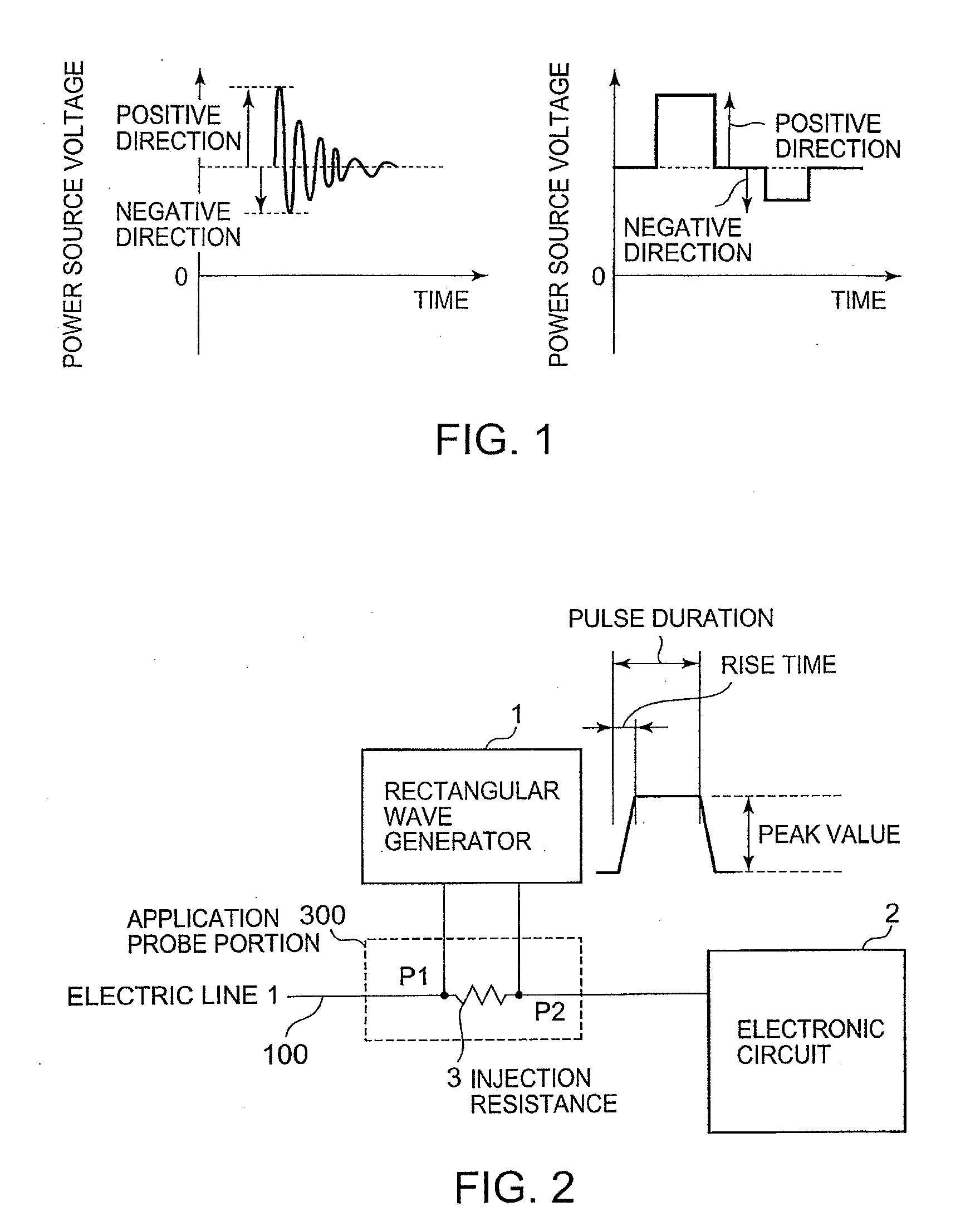
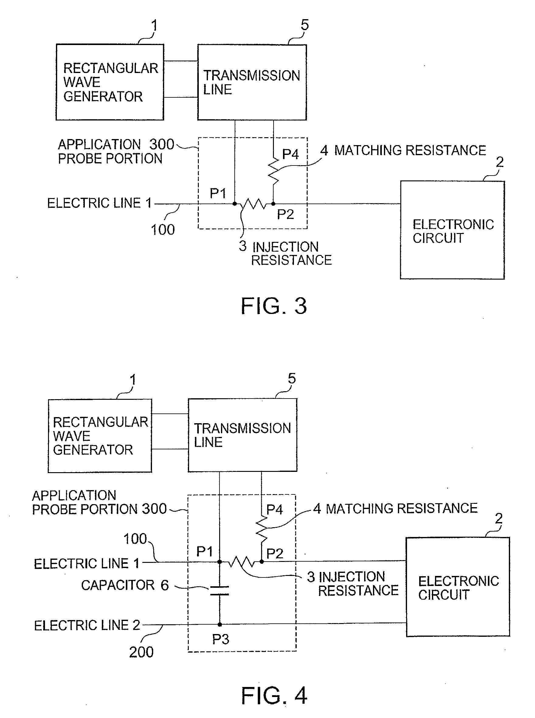
[0161]An example of the present invention will be described below with reference to FIG. 19. A TLP generator is used as a rectangular wave generator. Electric charges accumulated in a coaxial line are transmitted through a coaxial line having the same characteristic impedance as the TLP generator and applied to an application probe portion (300).

[0162]Generally, the rise time of a rectangular wave generated by a TLP generator can readily be adjusted to 1 ns or less. Conversely, the rise time may need to be adjusted to increase in some cases. Use of a filter FL can provide a rise time of 2 ns to 100 ns and a rise time longer than 100 ns under certain circumstances.

[0163]The application probe portion (300) is implemented by a matching resistance of 49Ω and an injection resistance of 1Ω, which match the characteristic impedances of 50Ω in the TLP generator and the coaxial line. Because a coaxial line having a characteristic impedance of 50Ω is generally used, a value of the matching re...


PUM


Abstract

The application methods in the related art cannot apply a sufficient voltage with a rectangular wave having a short rise time to an electronic circuit. Furthermore, electrostatic discharge test can apply a sufficient voltage but can only apply an oscillating waveform.A TLP generator is used as a rectangular wave generator. The sum of an injection resistance and a matching resistance is set so as to match the characteristic impedance of a transmission line for transmitting a rectangular wave to a test target. A capacitor is connected to a return line of the applied rectangular wave. With this configuration, stable application can be achieved. An error observation function of an electronic circuit gradually increases a peak value of the rectangular wave and determines the immunity based on an application voltage to cause an error for the first time.

Description

TECHNICAL FIELD:[0001]The present invention relates to a test apparatus for testing an immunity (noise resistance) of an electronic circuit in a case where a rectangular wave is used as noise.BACKGROUND ART[0002]Integration of electronic circuits has been developed along with reduction of the size and weight of electronic circuits. A power source voltage has been reduced along with miniaturization in LSI fabrication processes. Therefore, electronic circuits are relatively getting susceptible to noise. The immunity (noise resistance) of a device should be tested thoroughly, and various precautions should be taken prior to marketing of the device.[0003]An electrostatic discharge test described in Non Patent Literature 1 (IEC61000-4-2 (the international standard of electrostatic discharge)) is generally known as an immunity test to an impulse.[0004]Patent Literature 1 (Japanese Patent No. 3613269 (known patent of an immunity test)) discloses known technology of an immunity test.[0005]G...

Claims


Application Information

Patent Timeline
IPC IPC(8): G01R27/28
CPCG01R31/002G01R31/3004G01R31/2841
Inventor TSUKAGOSHI, TSUNEOWATANABE, TAKESHINAKAIE, TOSHIYUKIMATSUI, NOBUCHIKA
Owner RENESAS ELECTRONICS CORP
Why Eureka
Try Eureka