
Relaxation of a strained material layer with application of a stiffener

Active Publication Date: 2010-04-08
S O I TEC SILICON ON INSULATOR THECHNOLOGIES
View PDF3 Cites 24 Cited by
  • Summary
  • Abstract
  • Description
  • Claims
  • Application Information

AI Technical Summary

Benefits of technology

[0011]To achieve these and other advantages and in accordance with the purpose of the invention, as embodied herein, the disclosed embodiments remedy the aforementioned disadvantages, and permit fabrication of a layer of a material that is at least partially relaxed for electronics, optoelectronics or photovoltaics rapidly, effectively and in a practical manner.

Problems solved by technology

Nevertheless, the properties of these seed substrates are not always adapted to the materials from which one wishes to carry out the growth.
In fact, seed substrates may present, for example, a thermal expansion coefficient and a lattice parameter that are different from those of the materials from which one wishes to carry out growth, which produces a certain number of defects in the layer formed, such as cracks that may develop during the growth or cooling of the structure, or the presence of lattice defects that reduce the efficacy of the devices formed later, or even the compression stress or tension stress of the layer.
But these techniques do not yield completely satisfactory results, as the strained layer is not always or completely relaxed elastically.
In addition, when the material is compression strained, this elastic relaxation may lead to buckling of the material, the roughness and amplitude between the peaks and valleys of the buckled layer then cannot be reconciled with the desired utilizations.
When the material is tension strained, the relaxation often produces cracks and an increase in surface roughness.
It is possible that the film will fracture if the roughness exceeds a critical value.
But, in terms of heat treatment, relaxation remains partial in the initially strained material.
Optimization of the cycles combining these two variations is also planned but the relaxation method remains relatively long to put in place.

Method used


Image

  • Relaxation of a strained material layer with application of a stiffener
  • Relaxation of a strained material layer with application of a stiffener
  • Relaxation of a strained material layer with application of a stiffener

Examples


Embodiment Construction

[0028]Reference will now be made in detail to the present preferred embodiments, examples of which are illustrated in the accompanying drawings and accompanying text.

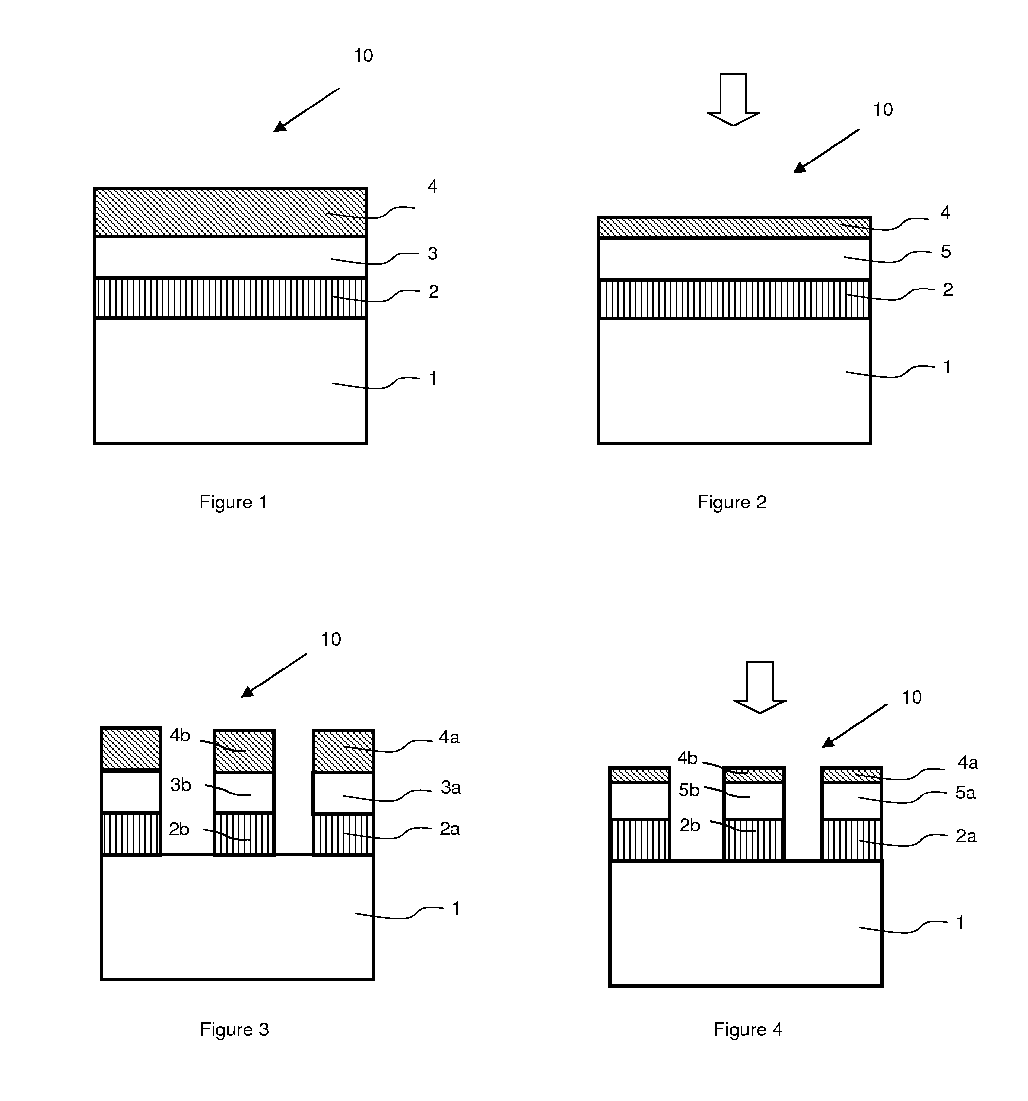
[0029]For purposes of illustration, and not limitation, FIG. 1 represents a structure 10 having a layer of strained material 3 situated between a reflow layer 2 and a stiffener layer 4. Preferably, structure 10 also includes a support substrate 1 on which the reflow layer 2 lies. Substrate 1 is adapted to reinforce the rigidity of the structure 10 during heat treatment. Heat treatment is applied to bring the reflow layer 2 to a temperature equal to or greater than its glass transition temperature during which the thickness of the stiffener layer 4 is progressively reduced, as illustrated in FIG. 2.

[0030]It is noted that a material is referred to as being strained respectively in tension or in compression in the interface plane with the material on which it lays when its lattice parameter is respectively greater than or ...


PUM


Abstract

The invention relates to methods of fabricating a layer of at least partially relaxed material, such as for electronics, optoelectronics or photovoltaics. An exemplary method includes supplying a structure that includes a layer of strained material situated between a reflow layer and a stiffener layer. The method further includes applying a heat treatment that brings the reflow layer to a temperature equal to or greater than the glass transition temperature of the reflow layer, and the thickness of the stiffener layer is progressively reduced during heat treatment. The invention also relates to an exemplary method of fabricating semiconductor devices on a layer of at least partially relaxed material. Specifically, at least one active layer may be formed on the at least partially relaxed material layer. The active layer may include laser components, photovoltaic components and / or electroluminescent diodes.

Description

CROSS-REFERENCE TO RELATED APPLICATIONS[0001]This patent application claims priority to French Patent Application No. 0805532, filed on Oct. 7, 2008. The aforementioned patent application is incorporated by reference herein in its entirety.BACKGROUND[0002]1. Field of the Invention[0003]The present invention relates to methods of fabricating a layer of strained material that is then caused to become at least partially relaxed for applications such as electronics, optoelectronics and photovoltaics. Disclosed methods generally include providing of a structure that includes a strained material layer situated between a reflow layer and a stiffener layer, and applying a heat treatment that brings the reflow layer to a temperature equal to or greater than the glass transition temperature of the reflow layer. In other aspects, the invention also relates to fabricating semi-conductor devices from the layer of material that is at least partially relaxed.[0004]2. Description of Related Art[000...

Claims


Application Information

Patent Timeline
IPC IPC(8): H01L21/20
CPCH01L21/02422H01L21/02488H01L21/187H01L21/02667H01L21/0254Y02E10/50H01L31/04
Inventor KONONCHUK, OLEG
Owner S O I TEC SILICON ON INSULATOR THECHNOLOGIES
Learn More