
Apparatus for converting wave energy into electrical energy

Active Publication Date: 2010-04-08
SHIN ICKSOO
View PDF26 Cites 32 Cited by
  • Summary
  • Abstract
  • Description
  • Claims
  • Application Information

AI Technical Summary

Benefits of technology

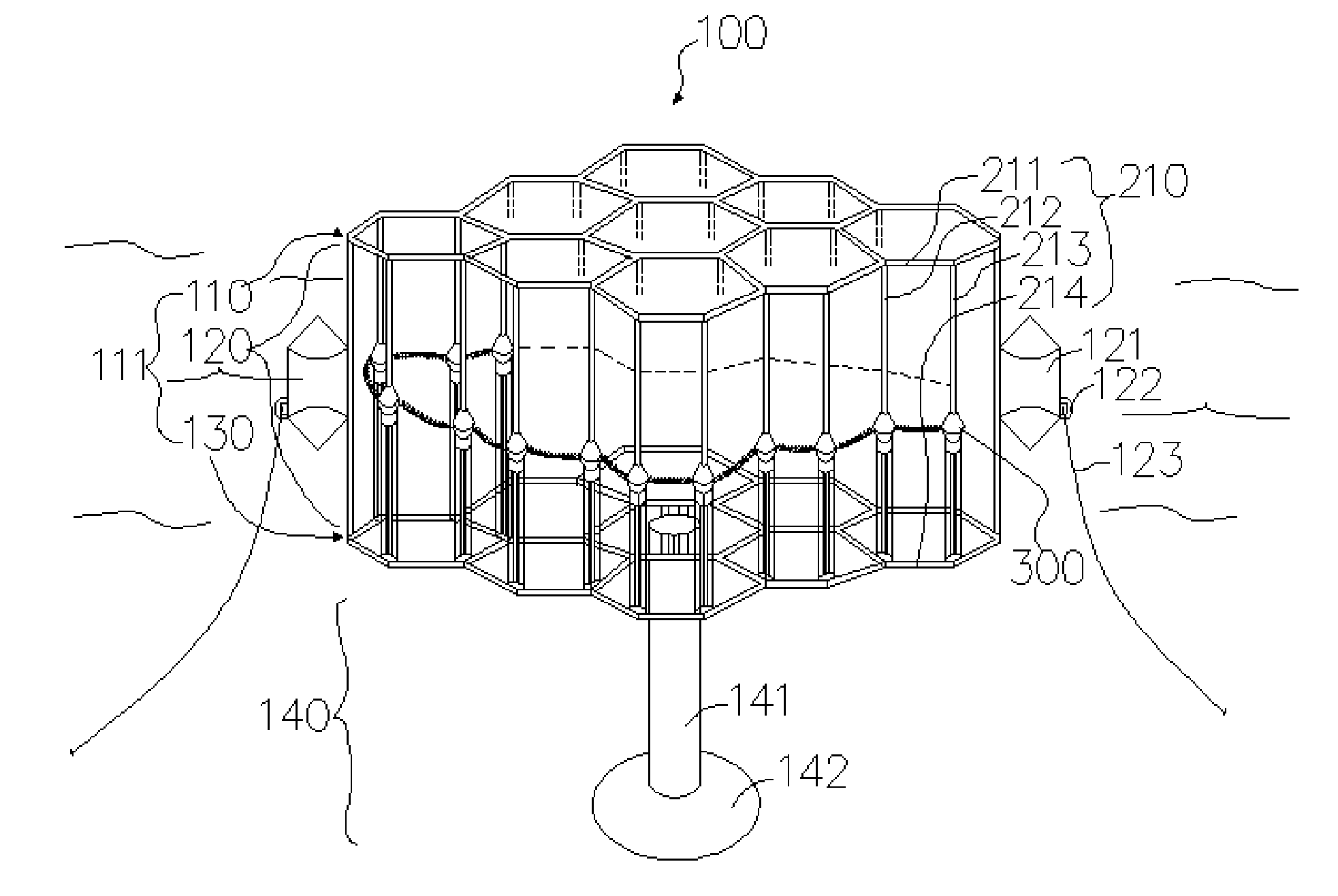
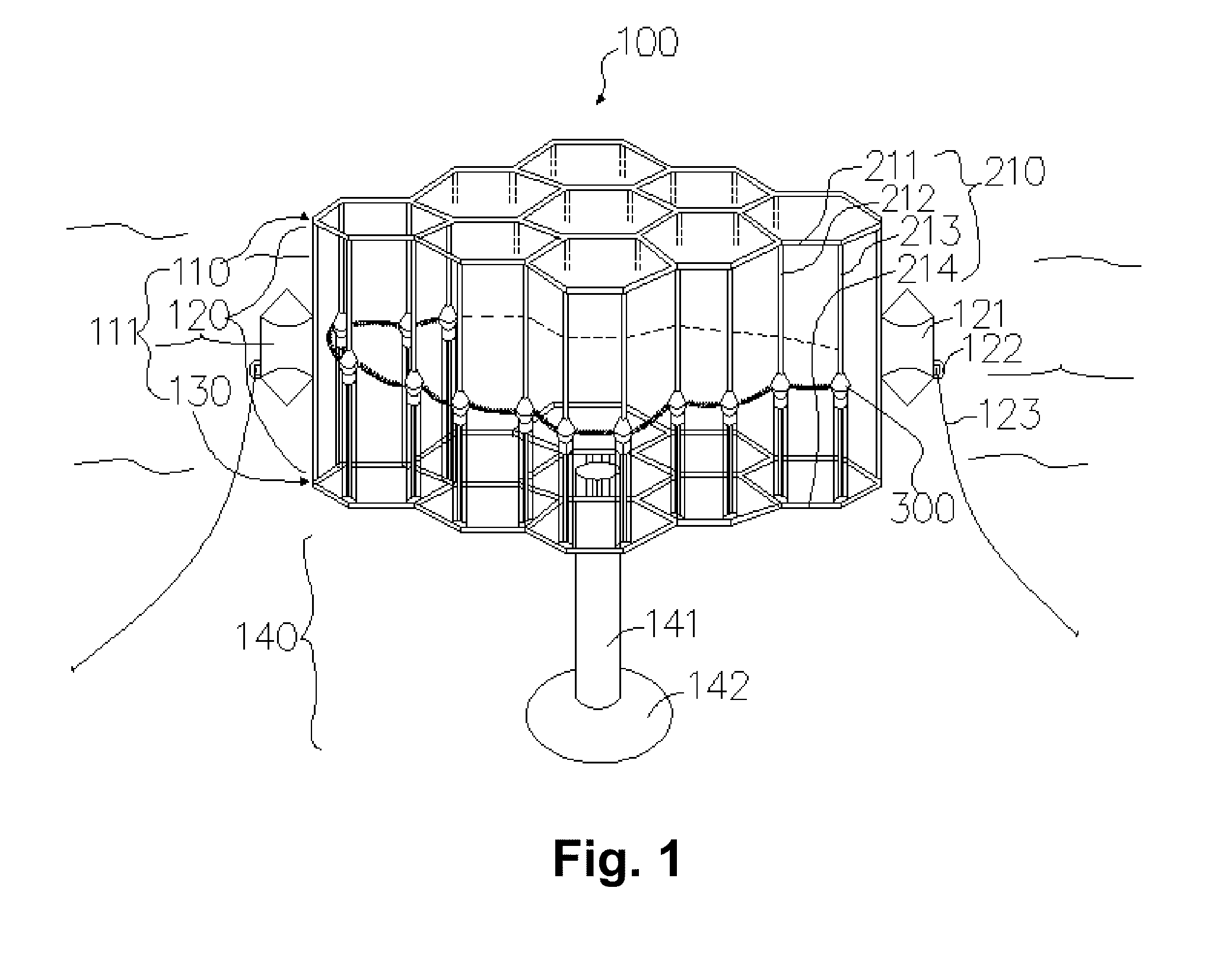
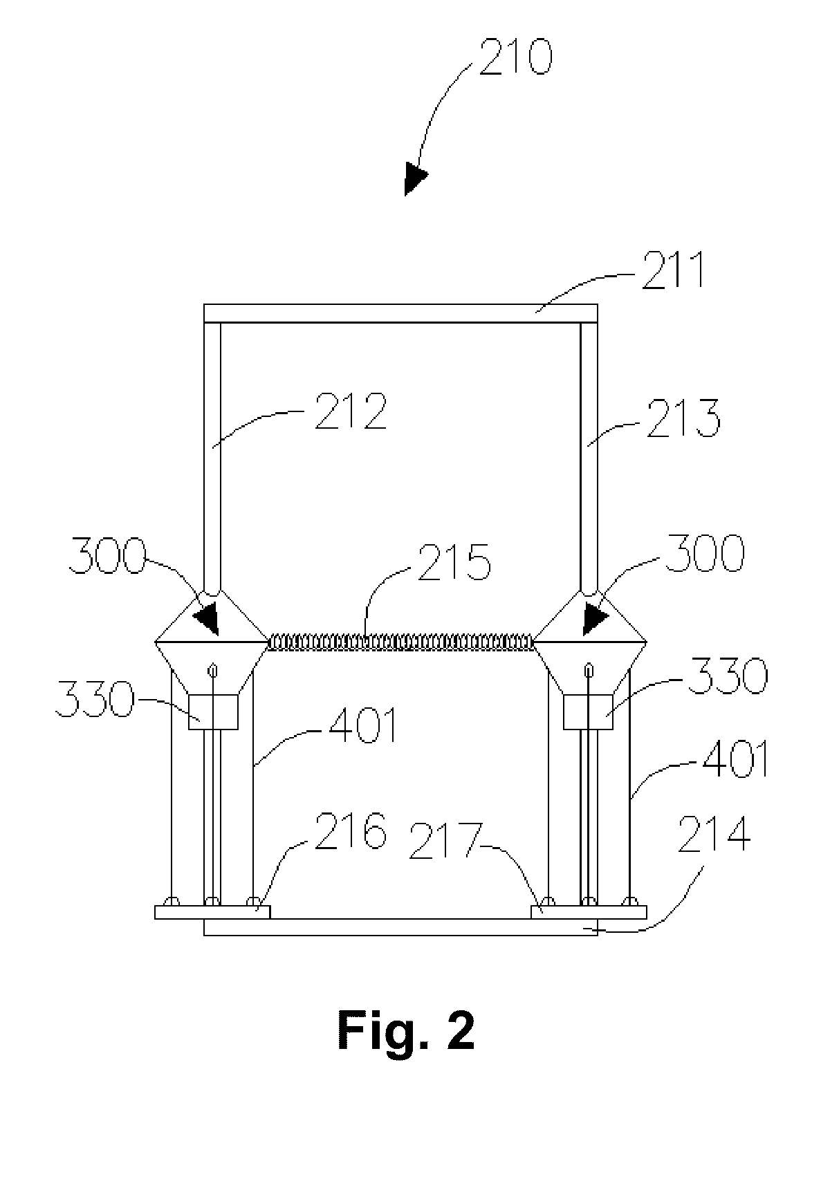
[0027]In one embodiment, an apparatus for converting wave energy into electrical energy is presented. The apparatus includes a wave power conversion module including a module case. An air sealing tube is formed in the module case for generally preventing fluids from entering the module case by compression of air in the module case. The air sealing tube extends downward from an interior of the module case through a bottom of the module case. A power transmission cable transmits electrical energy where one end of the power transmission cable passes through the air sealing tube. A cable reel rotatably supported within the module case winds and unwinds a portion of the power transmission cable in response to vertical motion. An elastic force means is joined to the cable reel for storing elastic force during the cable reel rotating to unwind the portion of the power transmission cable and for releasing the stored elastic force to enable the cable reel to wind the portion of the power transmission cable. An input shaft is joined to the cable reel and the elastic force means. A power transmission drive is joined to the input shaft for translating a bidirectional rotation of the input shaft into a unidirectional rotation. An output shaft is joined to the power transmission drive for transferring the unidirectional rotation. A generator is joined to the output shaft for generating electrical energy in response to the unidirectional rotation of the output shaft, and for transferring the electrical energy to the power transmission cable.
[0028]In another embodiment, an apparatus for converting wave energy into electrical energy is presented. The apparatus includes at least one wave power generation unit including an upper frame, a lower frame, means for joining the upper frame and the lower frame and means joined to the joining means for vertical motion in response to the wave energy. The vertical motion means includes an upper float covering, a lower float covering sealed to the upper float covering, means for guiding a cable from an interior of the vertical motion means downward through the lower float and means for power conversion contained within the vertical motion means. The power conversion means includes a module case, means for generally preventing fluids from entering the module case by compression of air in the module case. The preventing means extends downward from an interior of the module case through a bottom of the module case. The power conversion means further includes means for transmitting electrical energy through the preventing means and the guiding means, means for winding and unwinding a portion of the transmitting means in response to the vertical motion and means for storing elastic force during the means for winding and unwinding rotating to unwind for releasing the stored elastic force to enable the means for winding and unwinding rotating to wind. An input shaft is joined to the means for winding and unwinding and the storing means. The power conversion means further includes means for translating a bidirectional rotation of the input shaft into a unidirectional rotation, means for transferring the unidirectional rotation and means for generating electrical energy in response to the unidirectional rotation, and for transferring the electrical energy to the transmitting means.
[0029]In another embodiment, an apparatus for converting wave energy into electrical energy is presented. The apparatus includes at least one wave power generation unit including an upper frame, a lower frame and a plurality of float guides for joining the upper frame and the lower frame. At least one wave power generation float is joined to the float guides for vertical motion in response to the wave energy. The wave power generation float includes an upper float covering and a lower float covering sealed to the upper float covering. At least one cable guiding tube extends from an interior of the wave power float downward through the lower float and at least one wave power conversion module is contained within the wave power generation float. The wave power conversion module includes a module case and an air sealing tube formed in the module case for generally preventing fluids from entering the module case by compression of air in the module case. The air sealing tube extends downward from an interior of the module case through a bottom of the module case. A power transmission cable transmits electrical energy where one end of the power transmission cable passes through the air sealing tube and the cable guiding tube, and is joined to the lower frame. A cable reel is rotatably supported within the module case for winding and unwinding a portion of the power transmission cable in response to the vertical motion of the wave power generation float. An elastic force means is joined to the cable reel for storing elastic force during the cable reel rotating to unwind the portion of the power transmission cable and for releasing the stored elastic force to enable the cable reel to wind the portion of the power transmission cable. An input shaft is joined to the cable reel and the elastic force means. A power transmission drive is joined to the input shaft for translating a bidirectional rotation of the input shaft into a unidirectional rotation. An output shaft joined to the power transmission drive for transferring the unidirectional rotation. A generator is joined to the output shaft for generating electrical energy in response to the unidirectional rotation of the output shaft, and for transferring the electrical energy to the power transmission cable. In another emb

Problems solved by technology

However, these apparatuses have been economically unsuccessful.
However, a returning spring for rewinding the cable may be damaged when excessive external forces by big wave is exerted thereon.
When deploying this type of apparatus, large ocean space is required to prevent the cable from being tangled, leading to an increase in the deployment cost over a period of time.
However, since these apparatuses only use either the roll or pitch motion of wave energy, power output is less than a conventional coal or oil powered power plant.
However, the moment of inertia is not converted into electrical energy in these apparatuses and only one linear generator can be disposed on one axle that guides the movement of the float.
In wave power generation apparatuses, conventional sealing for rotating parts requires continuous maintenance, which increases operating cost over a given period of time.
Other apparatuses use a rigid structure for guiding the movement of a float; however, the rigid characteristics of the structure increases stress on the structure due to the continuous ocean wave motion.

Method used


Image

  • Apparatus for converting wave energy into electrical energy
  • Apparatus for converting wave energy into electrical energy
  • Apparatus for converting wave energy into electrical energy

Examples


Embodiment Construction

[0031]The present invention is best understood by reference to the detailed figures and description set forth herein.

[0032]Embodiments of the invention are discussed below with reference to the Figures. However, those skilled in the art will readily appreciate that the detailed description given herein with respect to these figures is for explanatory purposes as the invention extends beyond these limited embodiments. For example, it should be appreciated that those skilled in the art will, in light of the teachings of the present invention, recognize a multiplicity of alternate and suitable approaches, depending upon the needs of the particular application, to implement the functionality of any given detail described herein, beyond the particular implementation choices in the following embodiments described and shown. That is, there are numerous modifications and variations of the invention that are too numerous to be listed but that all fit within the scope of the invention. Also, ...


PUM


Abstract

An apparatus for converting wave energy into electrical energy includes a wave power generation unit including a frame and float guides. A wave power generation float is joined to the float guides for vertical motion in response to the wave energy. The wave power generation float includes at least one wave power conversion module. The wave power conversion module includes a module case and an air sealing tube formed in the module case for generally preventing fluids from entering the module case. A power transmission cable transmits electrical energy where one end of the power transmission cable passes through the air sealing tube and is joined to the frame. A cable reel winds and unwinds the power transmission cable. A power transmission drive translates a bidirectional rotation of an input shaft into a unidirectional rotation. A generator generates electrical energy in response to the unidirectional rotation.

Description

CROSS-REFERENCE TO RELATED APPLICATIONS[0001]The present Utility patent application claims priority benefit under 35 U.S.C. 119(a) of the South Korea patent application No. 10-2008-0098562 filed on 8 Oct. 2008. The contents of this related patent application are incorporated herein by reference for all purposes.FEDERALLY SPONSORED RESEARCH OR DEVELOPMENT[0002]Not applicable.REFERENCE TO SEQUENCE LISTING, A TABLE, OR A COMPUTER LISTING APPENDIX[0003]Not applicable.COPYRIGHT NOTICE[0004]A portion of the disclosure of this patent document contains material that is subject to copyright protection. The copyright owner has no objection to the facsimile reproduction by anyone of the patent document or patent disclosure as it appears in the Patent and Trademark Office, patent file or records, but otherwise reserves all copyright rights whatsoever.FIELD OF THE INVENTION[0005]The present invention relates generally to capturing waves and converting them into energy. More particularly, the inv...

Claims


Application Information

Patent Timeline
IPC IPC(8): F03B13/12
CPCF03B13/1865F05B2240/40F05B2240/917Y02E10/38F05B2250/283F05B2260/402F05B2260/4031F05B2240/931Y02E10/30F03B13/14F03B13/12
Inventor SHIN, ICKSOO
Owner SHIN ICKSOO
Learn More