
System and method for automatic communication lane failover in a serial link

a serial link and automatic communication technology, applied in the field of serial communication, can solve the problems of serial communication links using bundled serializer/deserializer (serdes) lanes experiencing lane failures, failure may take down the entire link, and the number of data bits may be reduced

Active Publication Date: 2010-04-01
ORACLE INT CORP
View PDF9 Cites 25 Cited by
  • Summary
  • Abstract
  • Description
  • Claims
  • Application Information

AI Technical Summary

Benefits of technology

[0005]Various embodiments of a system and method for automatic lane failover in a serial communication link are disclosed. In one embodiment, the system includes a first device coupled to a second device via a serial communication link. The serial communication link includes a plurality of communication lanes. The first device and the second device are configured to communicate by operating the serial communication link in a normal mode and a degraded mode. During operation in the normal mode, the first device and the second device may send frames of information to each other via the serial communication link. The fr

Problems solved by technology

Of the many components in a system, interconnects between devices may be subject to one or more lanes of a communication link failing.
For example, serial communication links using bundled serializer / deserializer (SerDes) lanes may experience lane failures.
In some systems, a lane failure may take down the entire link.
In other systems, a lane failure may require software intervention to recover.
However, software recovery mechanisms cannot generally prevent a system failure.
Thus software intervention may not be a satisfactory solution.
Further, in some systems, recovery may include a operating with degraded error protection capabilities.
Thus, many of the conventional recovery mechanisms available today do not meet many of the requirements of a highly reliable system.

Method used


Image

  • System and method for automatic communication lane failover in a serial link
  • System and method for automatic communication lane failover in a serial link
  • System and method for automatic communication lane failover in a serial link

Examples


Embodiment Construction

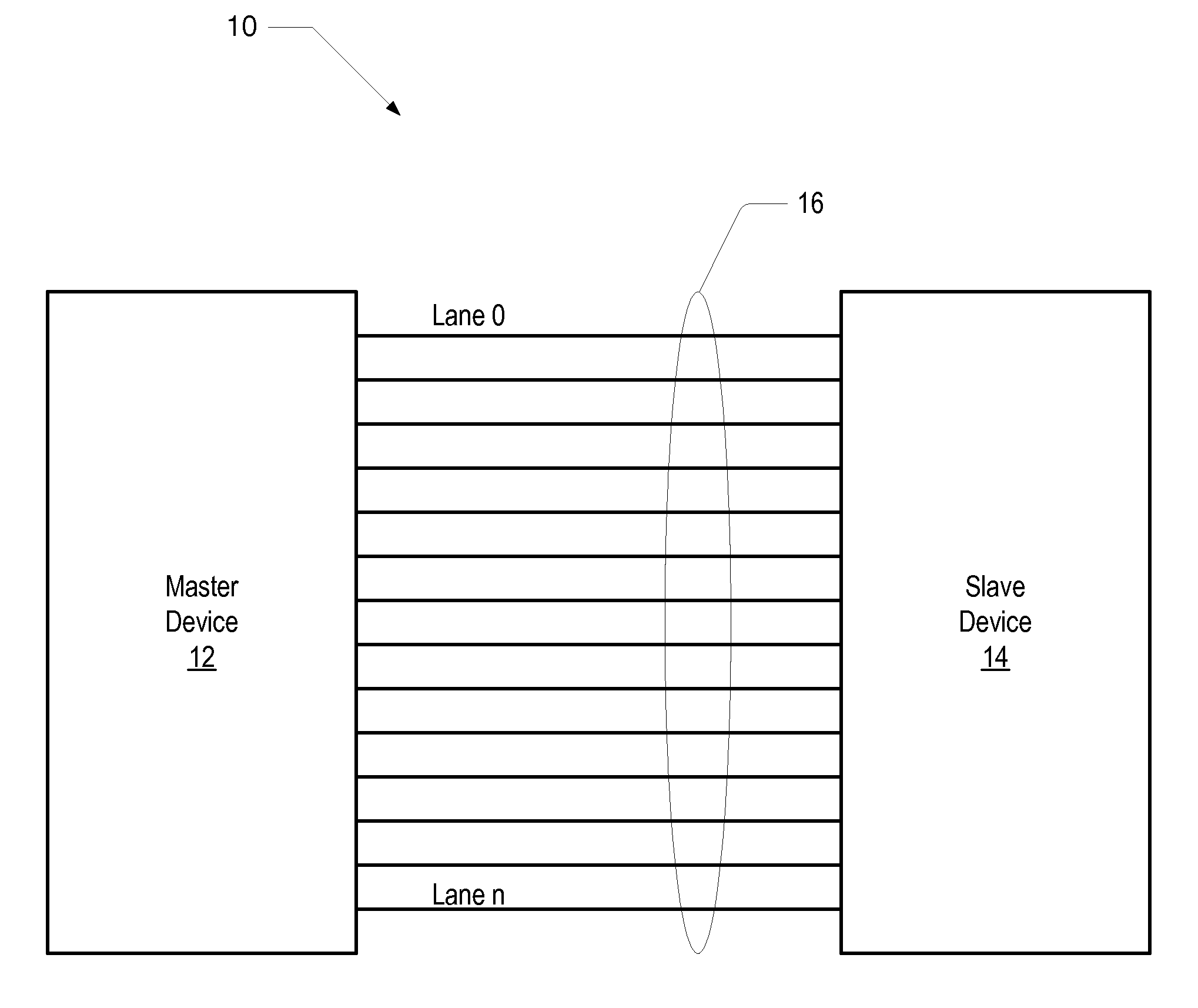
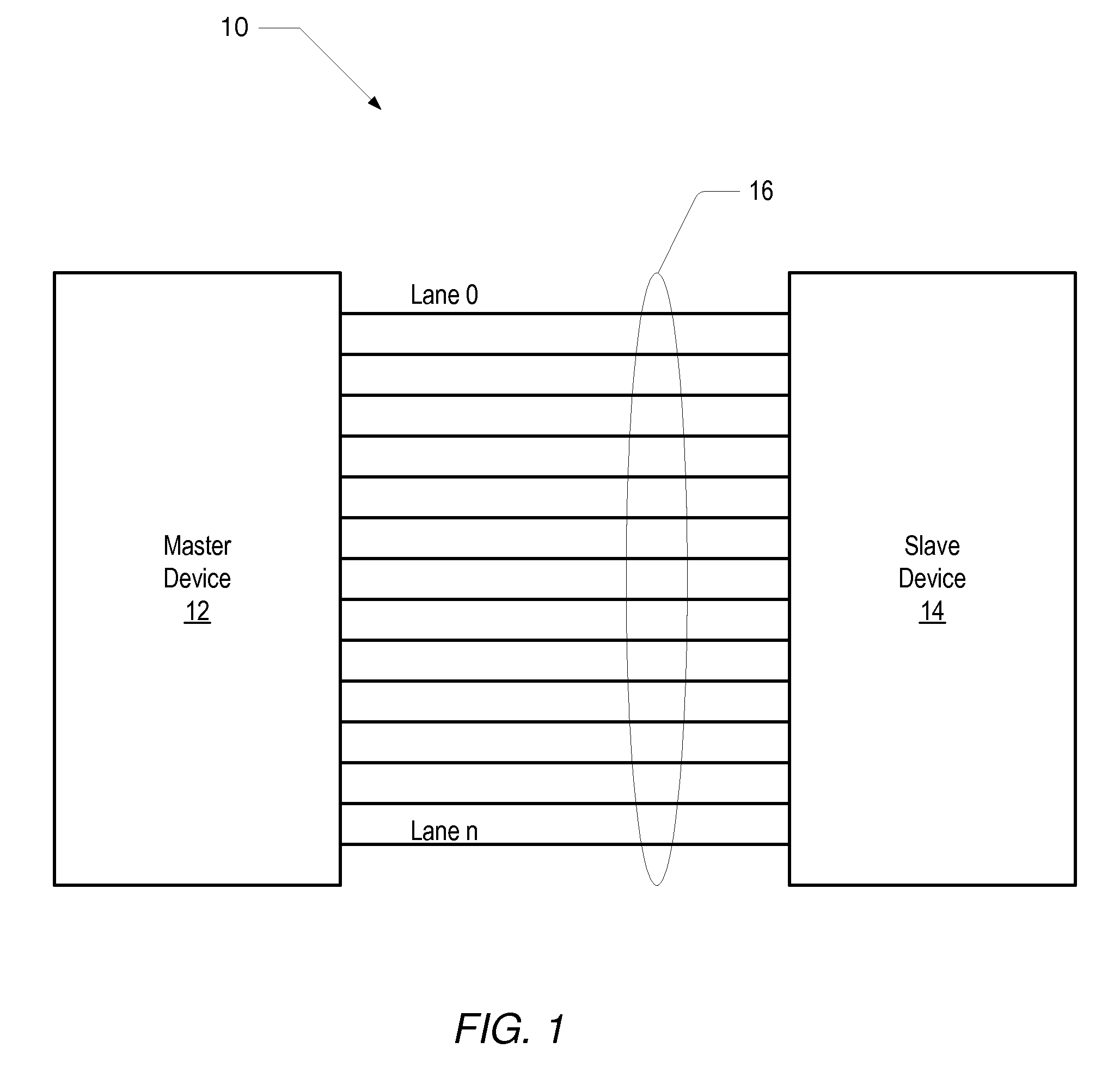
[0016]Turning now to FIG. 1, a block diagram of one embodiment of a system including devices interconnected by a serial communication link is shown. The system 10 includes a master device 12 coupled to a slave device 14 via a serial communication link 16. As shown, the link 16 includes a number of communication lanes designated lane 0 through lane n, where n may be any number.

[0017]In one embodiment, the master device 12 and the slave device 14 may both be processor devices configured to communicate to enable coherency operations. However, in other embodiments, master device 12 and slave device 14 may be any type of device that may communicate serially for any reason.

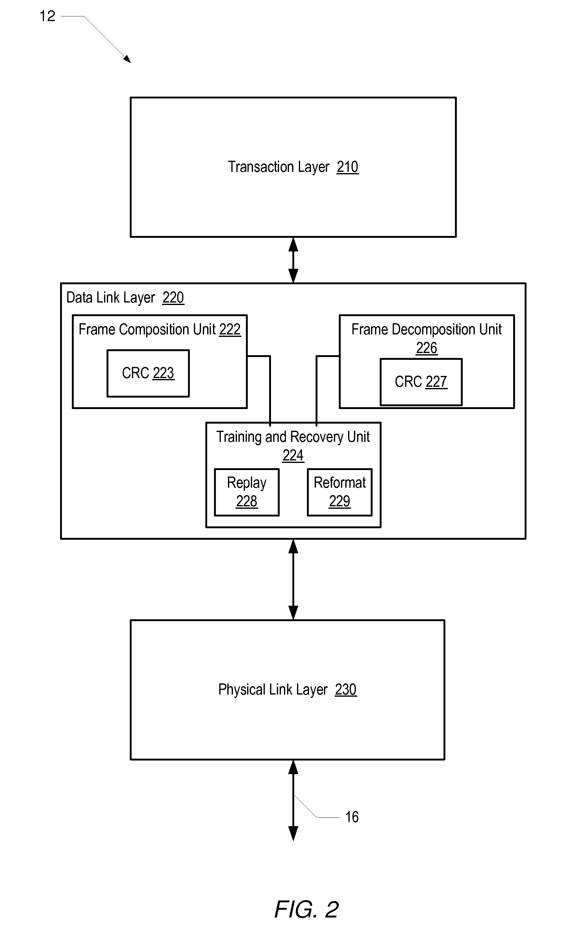
[0018]Accordingly, as shown in FIG. 2, each of master device 12 and slave device 14 may include a transaction layer 210, a data link layer 220, and a physical link layer 230. In one embodiment, the transaction layer 210 may comprise messages passed between devices to communicate memory and I / O requests, for example.

[001...


PUM


Abstract

A system for automatic lane failover includes a first device coupled to a second device via a serial communication link having a plurality of a communication lanes. The devices may communicate by operating the link in a normal mode and a degraded mode. During normal mode operation, the devices may send frames of information to each other via the serial communication link. Each frame of information may include a number of data bits and a number of error protection bits. In response to either device detecting a failure of one or more of the communication lanes, the first device may cause the serial communication link to operate in a degraded mode by removing the one or more failed communication lanes. In addition, each device may reformat and send the frame of information on the remaining communication lanes with fewer data bits and the same number of error protection bits.

Description

BACKGROUND OF THE INVENTION[0001]1. Field of the Invention[0002]This invention relates to serial communication and, more particularly, to automatic lane failure recovery.[0003]2. Description of the Related Art[0004]Highly available computer systems require fault tolerance on components that are likely to fail. Of the many components in a system, interconnects between devices may be subject to one or more lanes of a communication link failing. For example, serial communication links using bundled serializer / deserializer (SerDes) lanes may experience lane failures. In some systems, a lane failure may take down the entire link. In other systems, a lane failure may require software intervention to recover. However, software recovery mechanisms cannot generally prevent a system failure. The software recovery mechanism is usually triggered on a reboot, during which the software recovery mechanism may reconfigure the hardware. Thus software intervention may not be a satisfactory solution. ...

Claims


Application Information

Patent Timeline
IPC IPC(8): G06F11/00G06F13/40G06F3/00
CPCG06F13/4295H04L1/0057H04L1/0006
Inventor SIVARAMAKRISHNAN, RAMASWAMYTURULLOLS, SEBASTIANPHILLIPS, STEPHEN E.
Owner ORACLE INT CORP
Learn More