
Image drawing system, image drawing server, image drawing method, and computer program

a drawing system and image technology, applied in the field of image drawing systems, can solve the problems of narrow and limited movable range of avatars, difficult to render a large amount of transmitted image information on the virtual world three-dimensionally, and difficult to transmit a large amount of image information on the virtual world to a low-performance device, so as to reduce the communication load and the processing speed of the client terminal, and reduce the number of data communication times

Inactive Publication Date: 2009-09-24
IBM CORP
View PDF4 Cites 29 Cited by
  • Summary
  • Abstract
  • Description
  • Claims
  • Application Information

AI Technical Summary

Benefits of technology

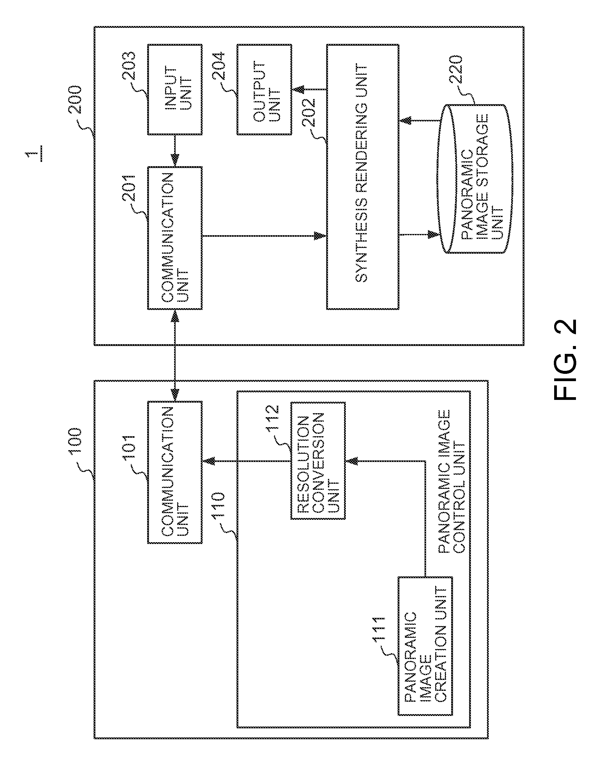
[0013]In this aspect of the present invention, a two-dimensional panoramic image (hereinafter called a panoramic image) around 360 degrees surrounding the avatar is created, whereby when the viewing angle of the avatar changes, there is no need for the client terminal to receive a panoramic image newly created by the image drawing server so that the number of data communication times can be reduced. Further, the panoramic image is created based on each of the three-dimensional objects in the nest configuration dividing the virtual world, where the created panoramic images are hierarchized in accordance with the distances from the viewpoint. Because the panoramic images are hierarchized, a panoramic image away from the avatar does not change much when the avatar moves, and therefore such a panoramic image can be reused without redrawing it. Thus, the communication load and the processing speed by the client terminal can be reduced.
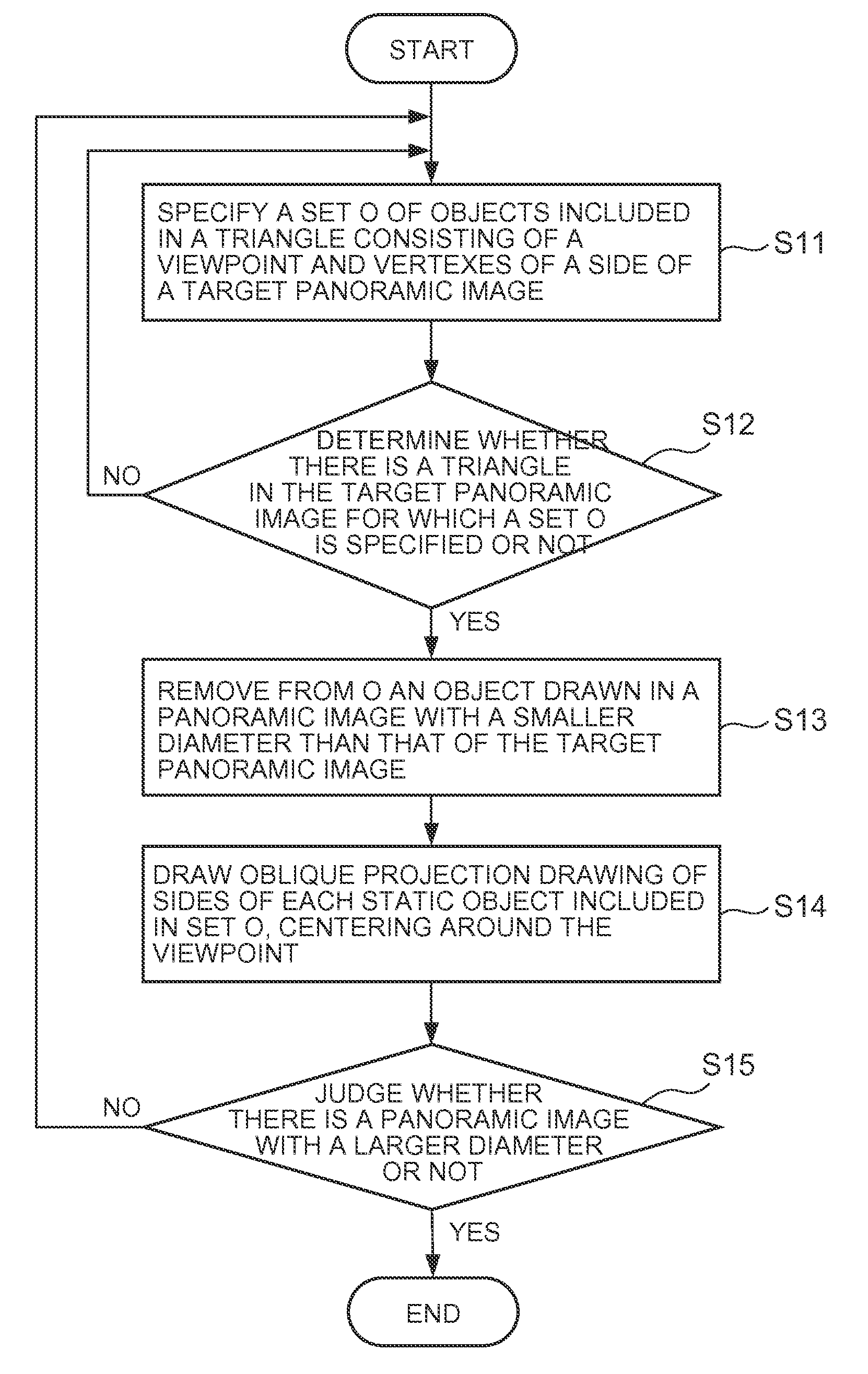
[0015]In still another aspect of the present invention, when the avatar moves closer to a side face of a closest vicinity three-dimensional object from the viewpoint, the three-dimensional object creation unit first creates a new closest vicinity three-dimensional object while setting a position in the vicinity of the avatar as a new viewpoint in response to a request from the client terminal. Then, the panoramic image creation unit creates new two-dimensional panoramic images corresponding to the newly created closest vicinity three-dimensional object and a second closest vicinity three-dimensional object, where the second closest vicinity three-dimensional object is second closest to the viewpoint and has been already created. Thus, when the avatar moves, the three-dimensional object creation unit recreates panoramic images based on the closest vicinity three-dimensional object and a second closest vicinity three-dimensional object only, and other panoramic images can be reused, so that the communication load and the processing speed by the client terminals can be reduced. The closest vicinity three-dimensional object and the panoramic images can be created beforehand speculatively by making predictions on a new vicinity center position based on the current movement of the avatar.

Problems solved by technology

However, it is difficult to transmit a large amount of image information on the virtual world to a low-performance device such as a mobile phone because of problems with the communication time period and communication traffic resulting from a narrow bus width for data transfer of a low-performance device.
Further, it is also difficult to render a large amount of transmitted image information on virtual world three-dimensionally because of the processing power of a low-performance device.
However, in Patent Document 1, the movable range of the avatar is narrow and limited.
Because of these problems, when the client terminal is a low-performance device such as a mobile phone, the three-dimensional virtual world cannot be provided thereto.

Method used


Image

  • Image drawing system, image drawing server, image drawing method, and computer program
  • Image drawing system, image drawing server, image drawing method, and computer program
  • Image drawing system, image drawing server, image drawing method, and computer program

Examples


Embodiment Construction

[0035]The following describes embodiments of the present invention with reference to the drawings.

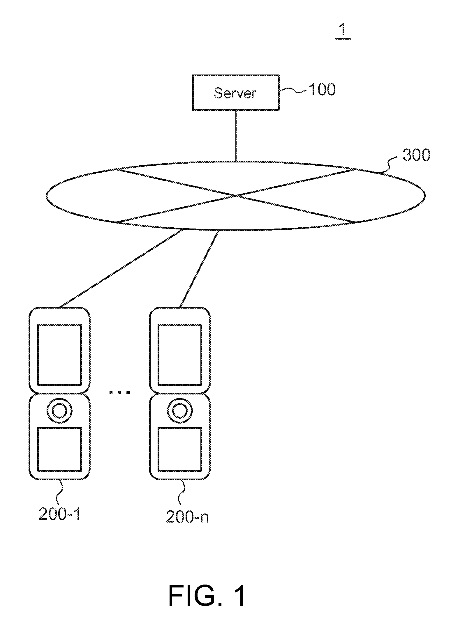
[0036]FIG. 1 illustrates the configuration of one embodiment of an image drawing system 1 to which the present invention is applied. Mobile phones 200-1, 200-2, . . . 200-n (hereinafter simply referred to as mobile phones 200 if there is no need to distinguish between the mobile phones 200-1 to 200-n) are client terminals. The mobile phones 200 are connected to a network 300, typically, the Internet or an intranet, thus enabling transmission and reception of data with respect to an image drawing server 100. Information on the user's operation using a mobile phone 200 is transmitted to the server via the network 300, whereas the mobile phones 200 can receive information held in the image drawing server 100 via the network 300. Although the client terminals are the mobile phones 200 in this example, they can be computers or low-performance devices other than the mobile phones 200. The num...


PUM


Abstract

An image drawing system, an image drawing server, an image drawing method, and a computer program product that provides a three-dimensional world to a client-terminal. The method includes: providing a viewpoint in the vicinity of an avatar and creating a three-dimensional object; performing a perspective projection of a static object to create a two-dimensional panoramic image; overlaying the two-dimensional panoramic image, information on a dynamic object, and an image of the avatar; and storing the two-dimensional panoramic image. The computer program product tangibly embodies instructions which when implemented causes a computer to execute the steps of the method. The system includes: a three-dimensional object creation unit; a panoramic image creation unit; a drawing unit for overlaying; and a panoramic image storage unit. The server includes: a reception unit; a three-dimensional object creation unit; a panoramic image creation unit; and a transmission unit.

Description

CROSS-REFERENCE TO RELATED APPLICATIONS[0001]This application claims priority under 35 U.S.C. § 119 to Japanese Patent Application No. 2008-73506 filed Mar. 21, 2008, the entire contents of which are incorporated by reference herein.BACKGROUND OF THE INVENTION[0002]1. Field of the Invention[0003]The present invention relates to an image drawing system, an image drawing server, an image drawing method, and a computer program for providing three-dimensional virtual world to at least one client terminal.[0004]2. Description of the Related Art[0005]In keeping with the trend of three-dimensional Internet and three-dimensional games, there is an increasing demand by users to access three-dimensional virtual world from a low-performance device such as a mobile phone. However, it is difficult to transmit a large amount of image information on the virtual world to a low-performance device such as a mobile phone because of problems with the communication time period and communication traffic ...

Claims


Application Information

Patent Timeline
Patent Type & Authority Applications(United States)
IPC IPC(8): G06T15/20G06F3/048G06F13/00G06F15/16H04B1/38
CPCG06N3/006G06T15/20G06T19/00
Inventor HORII, HIROSHIKAWACHIYA, KIYOKUNIKOSEKI, AKIRATAKAHASHI, TOSHIHIRO
Owner IBM CORP
Learn More