Time alignment methods and apparatus for polar modulation transmitters

a time alignment and transmitter technology, applied in the field of communication transmitters, can solve the problems of difficult to comply with out-of-band noise limitation standards, inefficient conversion of direct current (dc) power, and difficulty in the design of any type of transmitter, and achieve the effect of reducing bandwidth

Active Publication Date: 2010-04-01
PANASONIC CORP
View PDF3 Cites 12 Cited by
  • Summary
  • Abstract
  • Description
  • Claims
  • Application Information

AI Technical Summary

Benefits of technology

[0018]In one embodiment, the polar modulation transmitter further includes a bandwidth reduction circuit for reducing the bandwidths of either or both of the digital amplitude modulation and digital phase modulation signals. To account for timing discrepancies produced by different levels of processing performed by the bandwidth reduction circuit, a second delay element is provided to ensure that the bandwidth-reduced digital amplitude component and digital phase component signals in the AM and PM paths are synchronized at the outputs of the bandwidth reduction circuit.

Problems solved by technology

However, when the PA is backed off in this manner, it is very inefficient at converting direct current (DC) power from the transmitter's power supply to radio frequency (RF) energy, and linearity is achieved at the expense of power efficiency.
However, because it is operated in its nonlinear region, the PA 114 distorts the signals it amplifies.
However, if the predistortion is not performed properly, out-of-band signal energy is generated, making it difficult to comply with out-of-band noise limitation standards.
Controlling out-of-band signal energy can be difficult in the design of any type of transmitter.
It can be particularly difficult in the design of the polar modulation transmitter 100.
One difficulty relates to the fact that the digital amplitude and phase component signals ρ and θ are processed separately in independent AM and PM paths.
The different levels of processing can detrimentally affect the accuracy of the AM / AM and AM / PM correction processes, result in an increase in out-of-band signal energy, and, therefore, make it difficult, or in some cases even impossible, to comply with out-of-band noise limitation standards.

Method used


Image

  • Time alignment methods and apparatus for polar modulation transmitters
  • Time alignment methods and apparatus for polar modulation transmitters
  • Time alignment methods and apparatus for polar modulation transmitters

Examples


Embodiment Construction

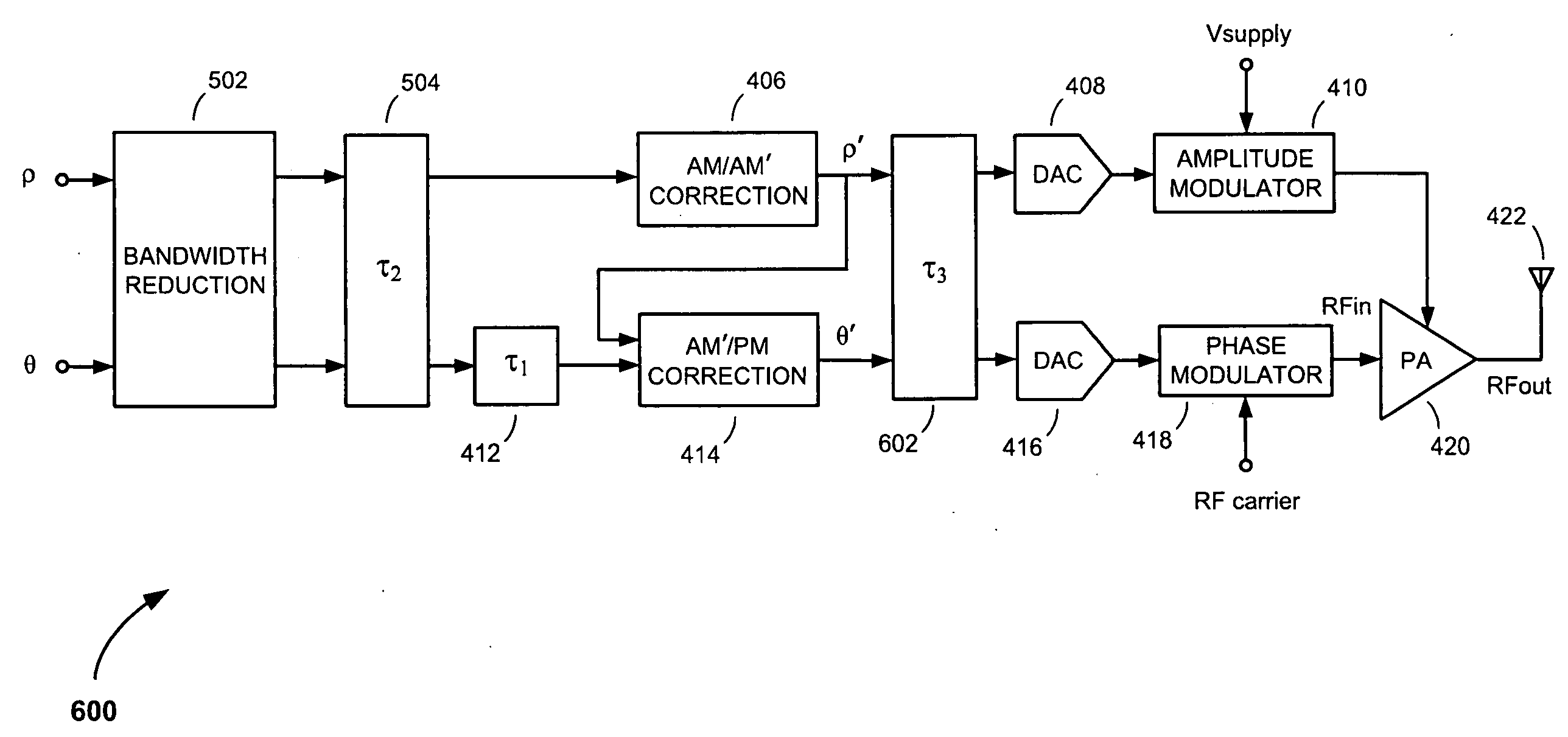
[0027]Referring to FIG. 4, there is shown a polar modulation transmitter 400, according to an embodiment of the present invention. The polar modulation transmitter 400 comprises a digital signal processor (DSP) 402, a Coordinate Rotation Digital Computer (CORDIC) converter 404; an amplitude modulation (AM) path including an amplitude modulation to amplitude modulation (AM / AM′) correction circuit 406, a first digital-to-analog converter (DAC) 408 and an amplitude modulator 410; a phase modulation (PM) path including a first delay element 412, an amplitude modulation to phase modulation (AM′ / PM) correction circuit 414, a second DAC 416 and a phase modulator 418; a power amplifier (PA) 420; and an antenna 422.

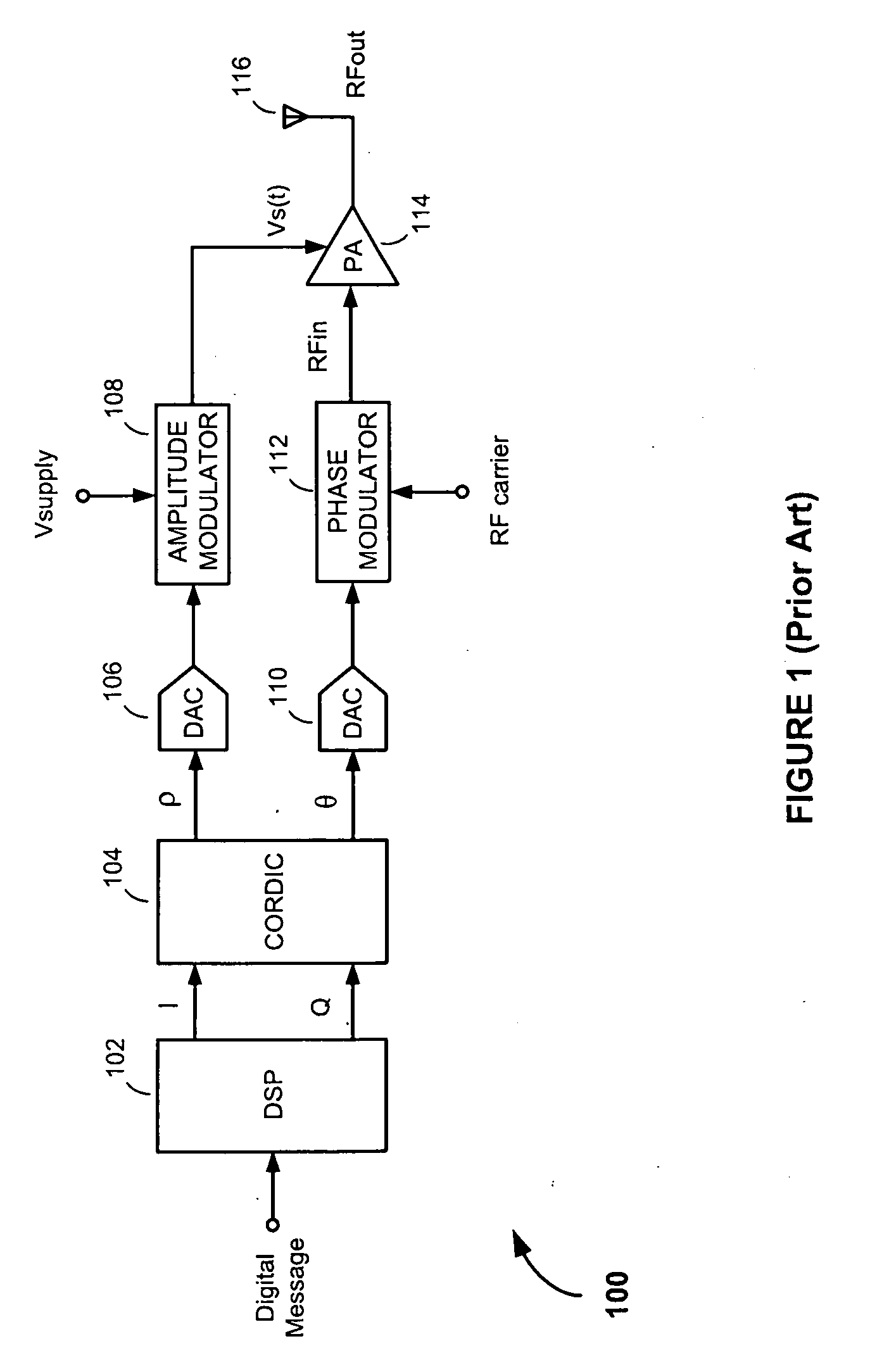
[0028]The DSP 402 operates to generate rectangular-coordinate in-phase and quadrature phase (i.e., I and Q) signals from bits in an incoming digital message to be transmitted. The I and Q signals are formatted in accordance with a predetermined modulation format, pulse-shaped to r...


PUM


Abstract

A polar modulation transmitter includes an amplitude modulation (AM) path with an amplitude modulation to amplitude modulation (AM/AM′) correction circuit and a phase modulation (PM) path with a delay element and an amplitude modulation to phase modulation (AM′/PM) correction circuit. The AM/AM′ correction circuit receives and predistorts a digital amplitude component signal depending on amplitudes of samples in the digital amplitude component signal, thereby generating a predistorted digital amplitude component signal. The delay element receives and delays a digital phase component signal, to generate a delayed digital phase component signal having a delay corresponding to the latency introduced by the AM/AM′ correction circuit. The AM′/PM correction circuit predistorts the delayed digital phase component signal depending on amplitudes of samples in the predistorted amplitude component signal, thereby generating a predistorted digital phase component signal.

Description

FIELD OF THE INVENTION[0001]The present invention relates to communications transmitters. More specifically, the present invention relates to methods and apparatus for methods and apparatus for aligning signals in polar modulation transmitters.BACKGROUND OF THE INVENTION[0002]Regulatory bodies and wireless standards organizations require radio frequency (RF) transmitters to transmit in certain predefined frequency bands. To increase the amount of information that can be transmitted in any given frequency band (i.e., to increase what is referred to as “spectral efficiency”), many existing and soon-to-be deployed wireless communication technologies, such as Wideband Code Division Multiple Access (W-CDMA), High-Speed Packet Access (HSPA) and Long Term Evolution (LTE) cellular technologies, employ nonconstant-envelope signals.[0003]In conventional quadrature-modulator-based transmitters, nonconstant-envelope signals must first be reduced before they are applied to the input of the trans...

Claims


Application Information

Patent Timeline
Patent Type & Authority Applications(United States)
IPC IPC(8): H04B1/02
CPCH03F1/3241H04B2001/0425H04B1/0475H03F1/3282
Inventor LEE, WAYNE S.WONG, TONY L.
Owner PANASONIC CORP
Why Eureka
Try Eureka