Apparatus and Method for Minimizing Undesirable Stepper Motor Rotor Motions

a technology of undesirable rotor motion and apparatus, applied in the direction of electric programme control, dynamo-electric converter control, instruments, etc., can solve the problems of increasing the tendency to oscillation, the probability of rotor snapping rather than moving, and the probability of rotor snapping, so as to reduce undesired motion and reduce undesired motion.

Active Publication Date: 2010-04-01
NOVANTA CORP
View PDF20 Cites 4 Cited by
  • Summary
  • Abstract
  • Description
  • Claims
  • Application Information

AI Technical Summary

Benefits of technology

[0008]In accordance with another preferred embodiment, a method for reducing undesired motions during initialization of a stepper motor having a rotary encoder coupled thereto is provided. In this preferred embodiment, the stepper motor comprises a rotor and phase windings under control of a microcontroller, and the method comprises applying currents to the phase windings to form a magnetic field vector in a direction; sensing a direction of rotor rotation; changing at least one motor phase current to rotate the magnetic field vector in a direction opposite to the direction of first sensed rotor rotation by a first electrical angle; sensing a direction of rotor rotation; changing at least one motor phase current to rotate the magnetic field vector to a next position in a direction opposite to the second sensed rotor rotation by a second electrical angle; and ending initialization, whereby the rotor is aligned with the magnetic field vector in its next position.
[0009]In accordance with yet another preferred embodiment, the method for reducin

Problems solved by technology

When power is initially applied to prior art stepper motors and associated drives there is a high probability that its rotor will snap, rather than move smoothly, into a detent position defined by its phase coils and or a magnetic path.
This characteristic of prior art stepper motors and associated motor drivers is undesirable because it can

Method used


Image

  • Apparatus and Method for Minimizing Undesirable Stepper Motor Rotor Motions
  • Apparatus and Method for Minimizing Undesirable Stepper Motor Rotor Motions
  • Apparatus and Method for Minimizing Undesirable Stepper Motor Rotor Motions

Examples


Embodiment Construction

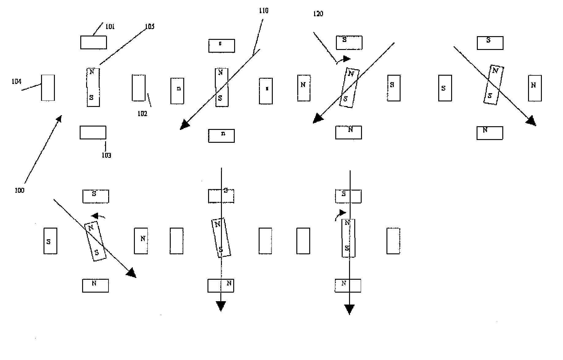
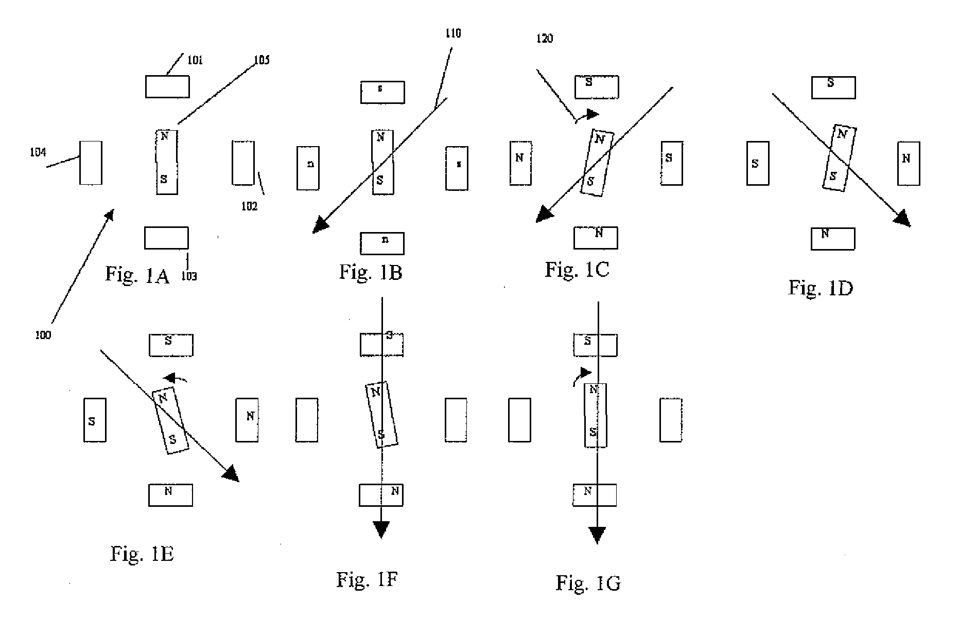
[0018]Generally speaking, in connection with a first preferred embodiment, the present invention is directed to a method and apparatus for reducing or eliminating turn on mechanical transients in a stepper motor resulting from an initial misalignment of an actual rotor position and a commanded rotor position which is based on phase currents of the motor.

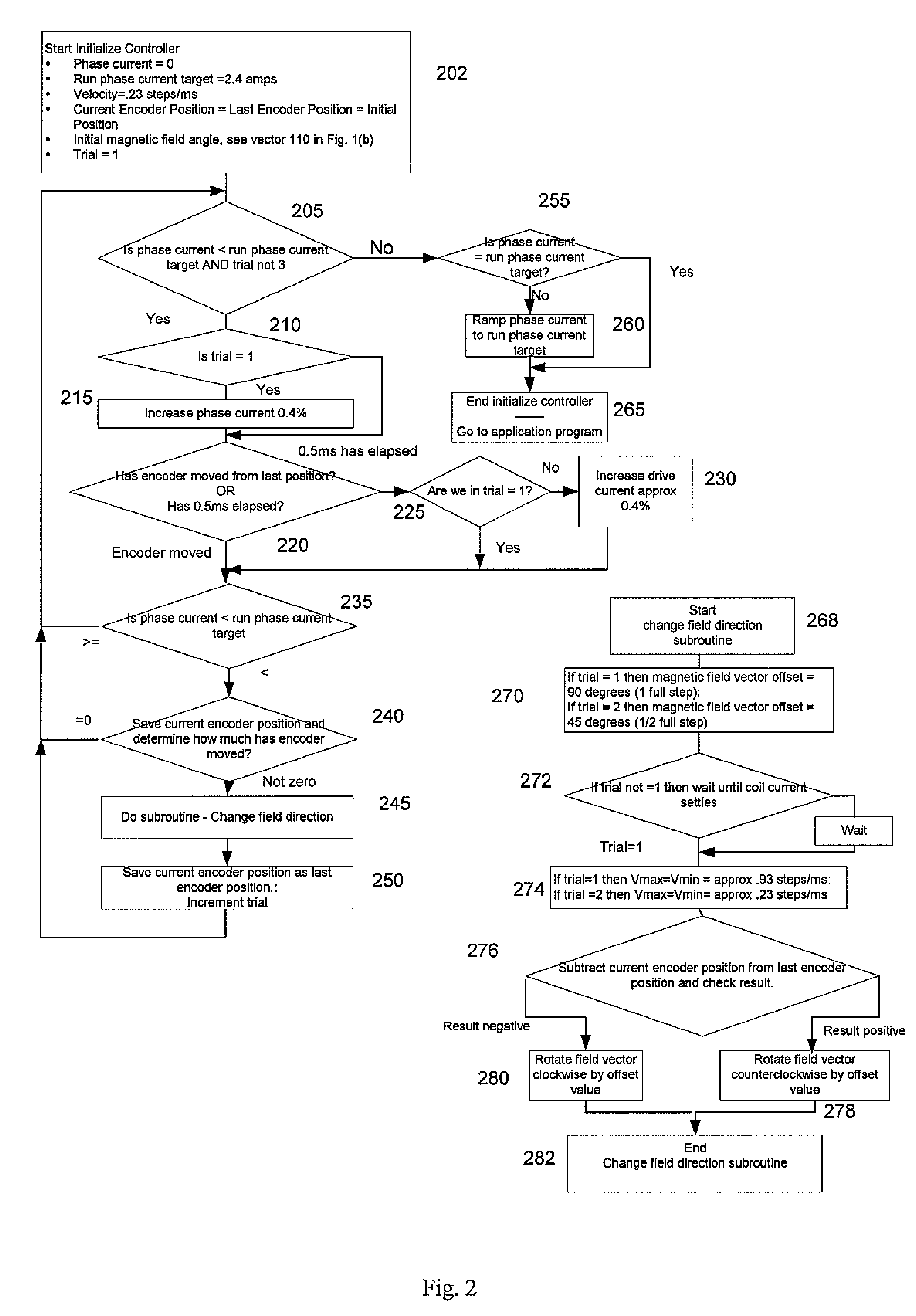
[0019]The present invention avoids problems with the prior art by gradually increasing phase currents while sensing both rotor motion and the direction of rotor motion and using the information to “zero in” on the closest detent that matches a commanded rotor position based on electrical angle of the phase currents.

[0020]In the preferred embodiments, the invention preferably comprises a shaft encoder mounted to a stepper motor shaft to sense the amount and direction of motor rotor motion as phase currents are increased. Having sensed motion, the currents are modified to change the direction of a magnetic field vector generated by the...


PUM


Abstract

An apparatus for reducing undesired motions during initialization of a stepper motor having a rotor and windings, the apparatus comprising a rotary encoder for sensing direction of rotor rotation; a microcontroller responsive to signals from the rotary encoder for generating bidirectional motor control waveforms having variable digital amplitude values; at least one motor driver for receiving the motor control waveforms and translating the waveforms to drive the motor windings; and wherein the translated waveforms urge the rotor in a first direction and then a second direction to locate a desired rotor position. A method of reducing undesired motions during initialization of a stepper motor having a rotary encoder coupled thereto comprises applying currents to the phase windings to form a magnetic field vector in a direction; sensing a direction of rotor rotation; changing at least one motor phase current to rotate the magnetic field vector in a direction opposite to the direction of first sensed rotor rotation by a first electrical angle; sensing a direction of rotor rotation; changing at least one motor phase current to rotate the magnetic field vector to a next position in a direction opposite to the second sensed rotor rotation by a second electrical angle; and ending initialization, whereby the rotor is aligned with the magnetic field vector in its next position.

Description

BACKGROUND OF THE INVENTION[0001]1. Field of the Invention[0002]This invention generally relates to the field of stepper motors and more particularly to an apparatus for and method of, electronic stepper motor control when power is first applied to a stepper motor.[0003]2. Background of the Invention[0004]When power is initially applied to prior art stepper motors and associated drives there is a high probability that its rotor will snap, rather than move smoothly, into a detent position defined by its phase coils and or a magnetic path. The reason is that there are typically 4 natural detent (rest) states for each 360 electrical degrees (4 steps) of motor driver output signal. If the state of a motor driver signal at power up does not match the initial rest state of the rotor, the rotor will snap to the position called for by the state of the motor driver as the motor coils are energized.[0005]This characteristic of prior art stepper motors and associated motor drivers is undesirab...

Claims


Application Information

Patent Timeline
IPC IPC(8): G05B19/40
CPCH02P1/163H02P8/32H02P8/04
Inventor SERVIDONE, FRANCESCO
Owner NOVANTA CORP
Why Eureka
Try Eureka